Communication Control Method and Wireless Communication Apparatus

a communication control and wireless communication technology, applied in the field of network systems, can solve the problems of inability to send and receive meaningful data upon changing over the communication mode, and the time-consuming and laborious to send and receive data, so as to ensure the compatibility of data

Active Publication Date: 2008-10-23
CANON KK
View PDF22 Cites 66 Cited by
  • Summary
  • Abstract
  • Description
  • Claims
  • Application Information

AI Technical Summary

Benefits of technology

[0014]An object of the present invention is to provide a communication control method, as well as a wireless communication apparatus for implementing this method, whereby even if a wireless communication apparatus is a wireless communication apparatus that does not possess a sophisticat

Problems solved by technology

As a consequence, the sending and receiving of data takes time.
However, even if data can be sent and received in a link layer, the sending and receiving of meaningful data cannot be performed upon cha

Method used


Image

  • Communication Control Method and Wireless Communication Apparatus
  • Communication Control Method and Wireless Communication Apparatus
  • Communication Control Method and Wireless Communication Apparatus

Examples


first embodiment

[0027]

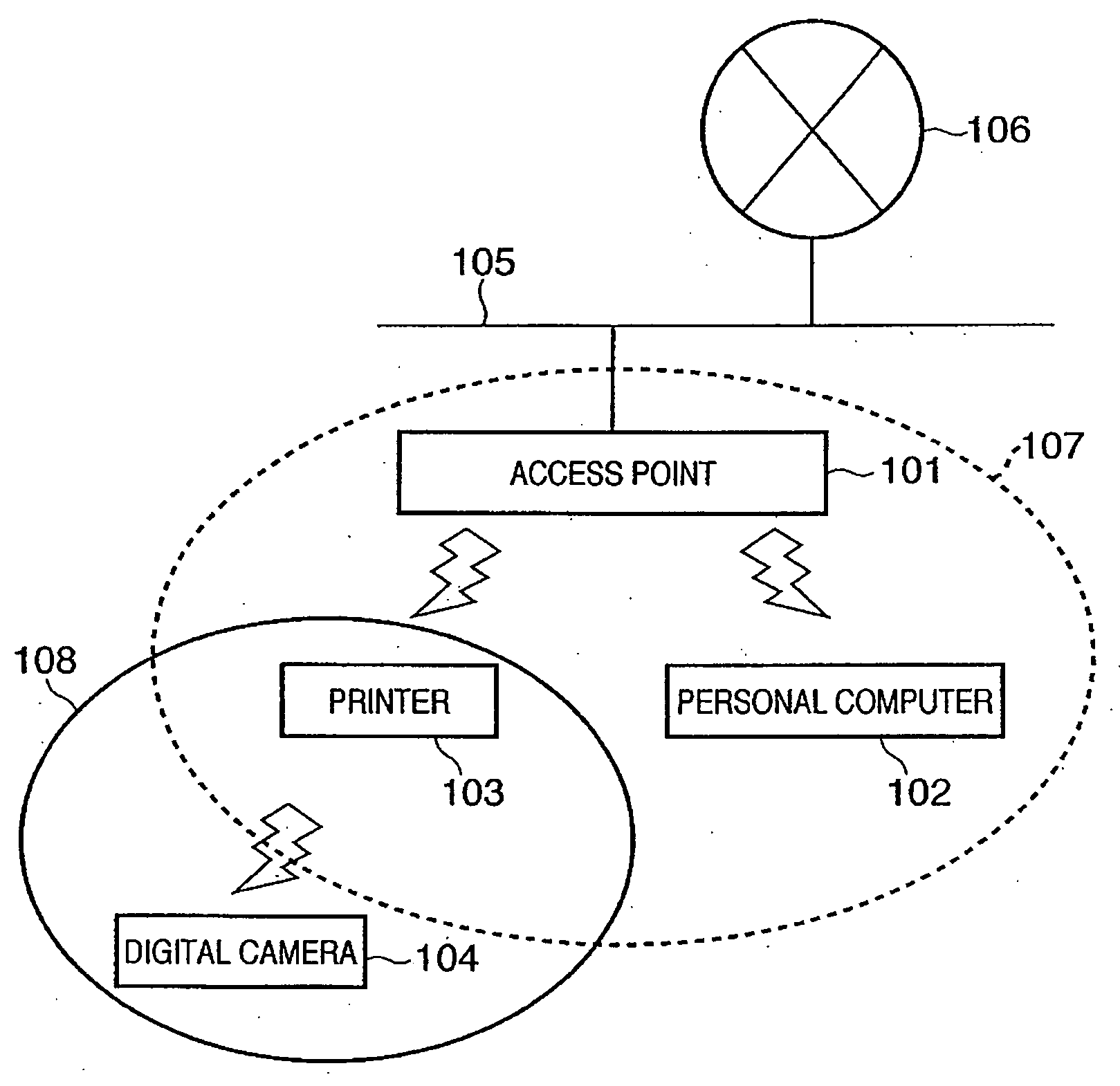
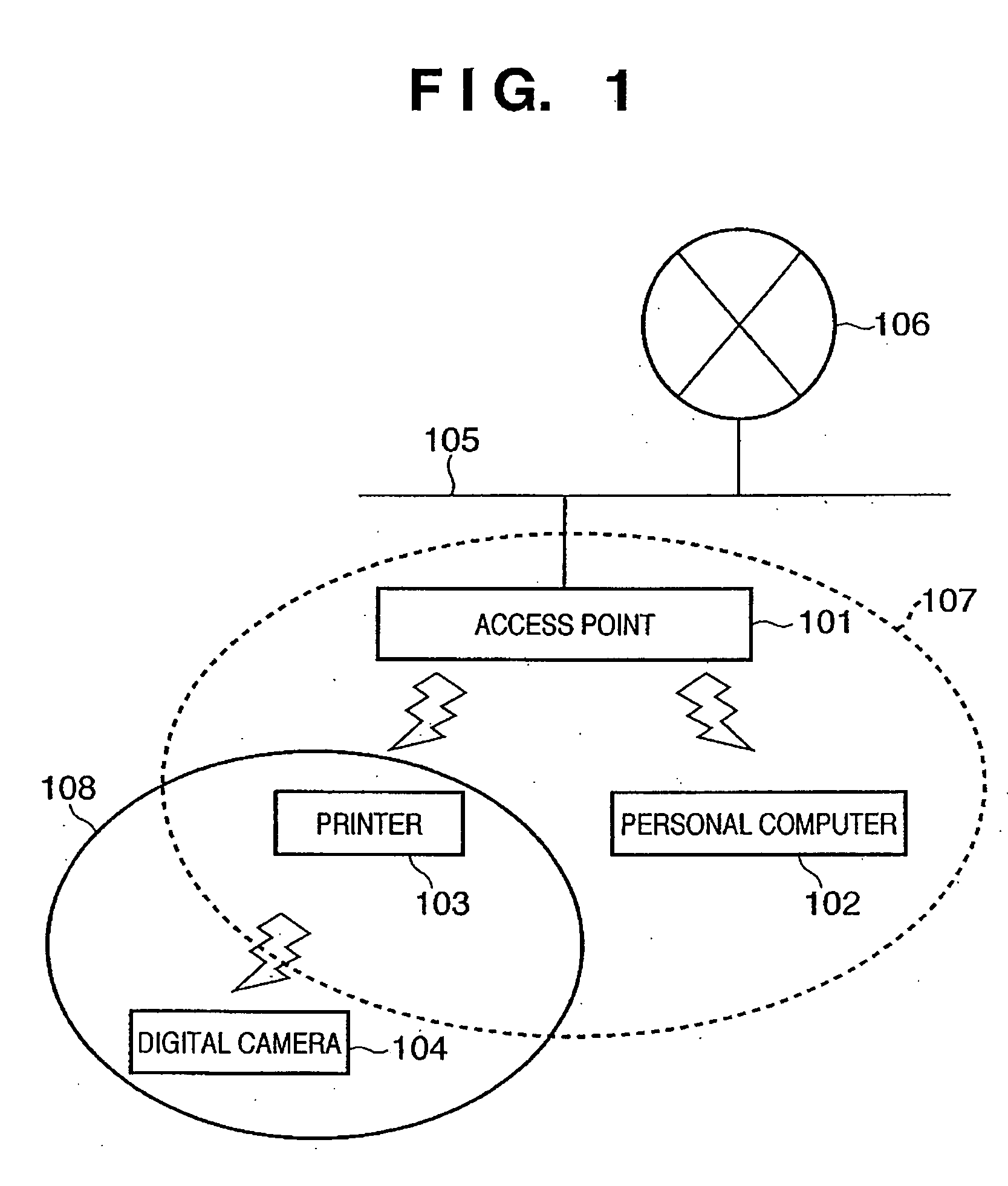
[0028]FIG. 1 is a schematic view useful in describing the form of a network system to which the present invention is applied. The network system of FIG. 1 comprises an access point 101, a personal computer 102, a printer 103, a digital camera 104, a wired line 105 and the Internet 106. The access point 101, which is a central control apparatus in the infrastructure mode (also referred to as a “first communication mode”), controls the communication of each connected device and relays the data transmitted by each device. The access point 101 is connected to the Internet 106 via a wired line. The personal computer 102 has a communication function for performing communication in the first communication mode with the Internet and other terminals via the access point 101. The printer 103, which has a communication function, is capable of printing data that has been received via the access point in the infrastructure mode and data that has been transmitted from a directly connected t...

first modification of embodiment

[0056]The printer 103 may temporarily delete the function table 201a of FIG. 5 immediately before the beacon search is started at step 401 and may construct the function table 201a afresh. In this case, it is preferred that once communication in the ad-hoc mode has started, the printer 103 conduct a function search with regard all discovered terminals that are the transmission sources of beacons in the ad-hoc mode. The reason for this is that since the printer 103 processes a print request from one digital camera in the processing path illustrated in FIG. 4, there is the possibility that there will be a wireless communication terminal (digital camera) for which a print request is not processed or a wireless communication terminal (digital camera) that will be left standing for a prolonged period of time. Accordingly, in a case where it is determined at step 408 in FIG. 4 that there is no succeeding data, control returns to step 404 and a function search is executed with respect to t...

second modification of embodiment

[0058]A function search is initiated at step 404 in FIG. 4 from the printer 103 equipped with the communication function. On the other hand, a connection in the ad-hoc mode may be sensed, as by receiving a frame that is exchanged at the time of a connection at a terminal connected to the printer 103, and this may serve as a trigger to start the function search.

[0059]Further, instead of a beacon-frame search at step 401, a beacon information request and response sequence may be performed. In this case, the printer 103 transmits a beacon-information request frame that requests transmission of at least an SSID and communication mode. A wireless communication terminal that has received this beacon-information request frame transmits a beacon-information response frame, which contains at least an SSID and communication mode, to the terminal (printer 103) that transmitted the beacon-information request frame. The printer 103 that has received the beacon-information response frame creates ...


PUM


Abstract

A printer (103) belongs to a service set (107) and communicates via an access point (101) in the infrastructure mode. The printer (103) searches for a beacon periodically. If a beacon is received from a terminal such as a digital camera (104), the printer registers the terminal address, service-set identifier and communication mode, which are contained in the beacon, in a function table. The printer sends each terminal, which has been registered in the function table, a frame that is for searching for a terminal that has a required function. If the response to the frame is positive, then the printer registers the fact that the search succeeded in the function table. A similar function search is conducted also by a digital camera (104) for which a print command has been issued, and the digital camera creates a function table. If there is a terminal (a printer) having the required function, the digital camera (104) transmits print data to this terminal.

Description

TECHNICAL FIELD[0001]This invention relates to a network system in which it is possible for a wireless communication apparatus (a mobile station) to communicate in a communication mode with the intermediary of a master station (base station) and a communication mode without the intermediary of a master station (base station). More particularly, the invention relates to a network system in which a digital camera and a printer, for example, are connected by a wireless LAN system, which is compliant with IEEE 802.11, having different network configurations, namely an infrastructure mode and an ad-hoc mode.BACKGROUND ART[0002]A communication method that provides a first communication mode (infrastructure mode), in which wireless communication is performed between terminals via a master station, and a second communication mode (ad-hoc mode), in which data is sent and received directly between terminals, is defined by the IEEE 802.11 standard.[0003]In the IEEE 802.11 standard, the frequen...

Claims


Application Information

Patent Timeline
IPC IPC(8): H04B7/26H04L12/28H04W8/00H04W28/00H04W48/08H04W48/16H04W60/00H04W74/04H04W74/08H04W76/02H04W84/12H04W88/06H04W92/18
CPCH04N1/00278H04N1/33307H04N1/33369H04N2201/0015H04N2201/0055H04N2201/0084H04W8/005H04W48/08H04W48/16H04W60/00H04W76/02H04W88/06H04W92/18H04W76/10
Inventor YOSHIDA, JUN
Owner CANON KK
Why Eureka
Try Eureka