
Puncturing system

a puncturing system and puncturing technology, applied in the field of puncturing systems, can solve the problems of heightened pain sensation, many users, difficult to tolerate waiting time, etc., and achieve the effect of facilitating visual control, facilitating learning, and facilitating correct puncturing system handling

Active Publication Date: 2008-10-23
ROCHE DIABETES CARE INC
View PDF26 Cites 110 Cited by
  • Summary
  • Abstract
  • Description
  • Claims
  • Application Information

AI Technical Summary

Benefits of technology

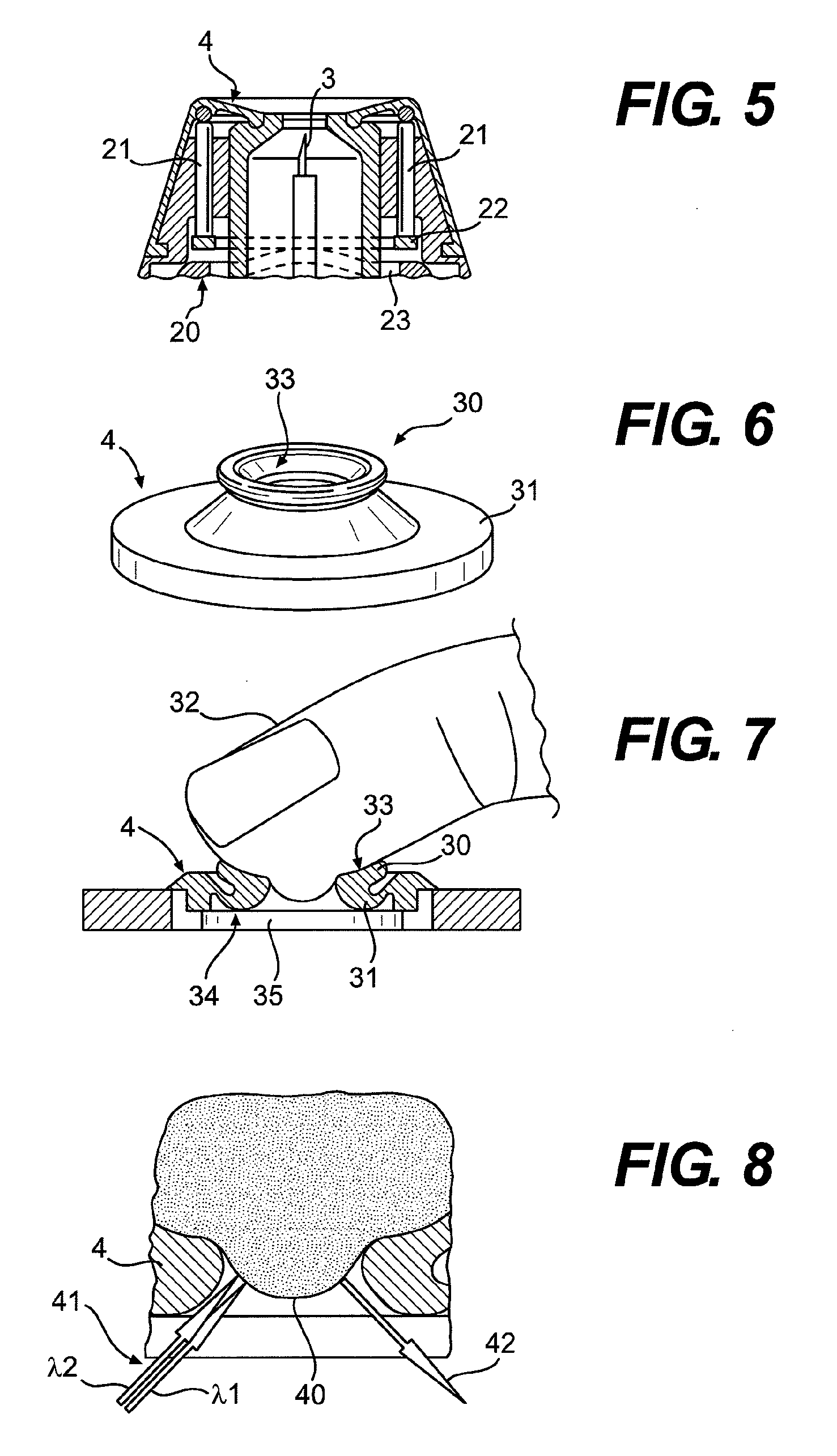
[0020]A testing facility can be used to give the user feedback in this regard such that the correct handling of the puncturing system can be made easier and quicker to learn. The testing facility preferably facilitates a visual control of the press-on part touching against the body part and / or of the body part touching against the press-on part to be made. For this purpose, for example, a camera can be integrated into the puncturing device such that a corresponding picture can be recorded and displayed by means of a display facility. A visual control can also be facilitated by means of passive optical elements, for example, mirrors and / or lenses instead of a camera.

Problems solved by technology

It has been found that automatic triggering of the puncturing motion by a testing facility in the form of a pressure sensor, such as is the case, for example, in the puncturing system known from U.S. Pat. No. 5,879,311, is unpleasant for many users for psychological reasons and may even lead to a heightened sensation of pain.
For many users, this waiting time is difficult to tolerate, unpleasant, and makes the puncture seem more painful.

Method used


Image

  • Puncturing system
  • Puncturing system
  • Puncturing system

Examples


Embodiment Construction

[0035]The embodiments of the present invention described below are not intended to be exhaustive or to limit the invention to the precise forms disclosed in the following detailed description. Rather, the embodiments are chosen and described so that others skilled in the art may appreciate and understand the principles and practices of the present invention.

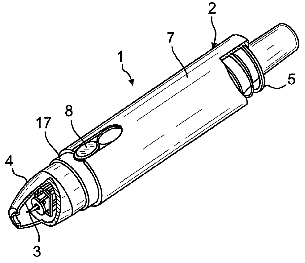
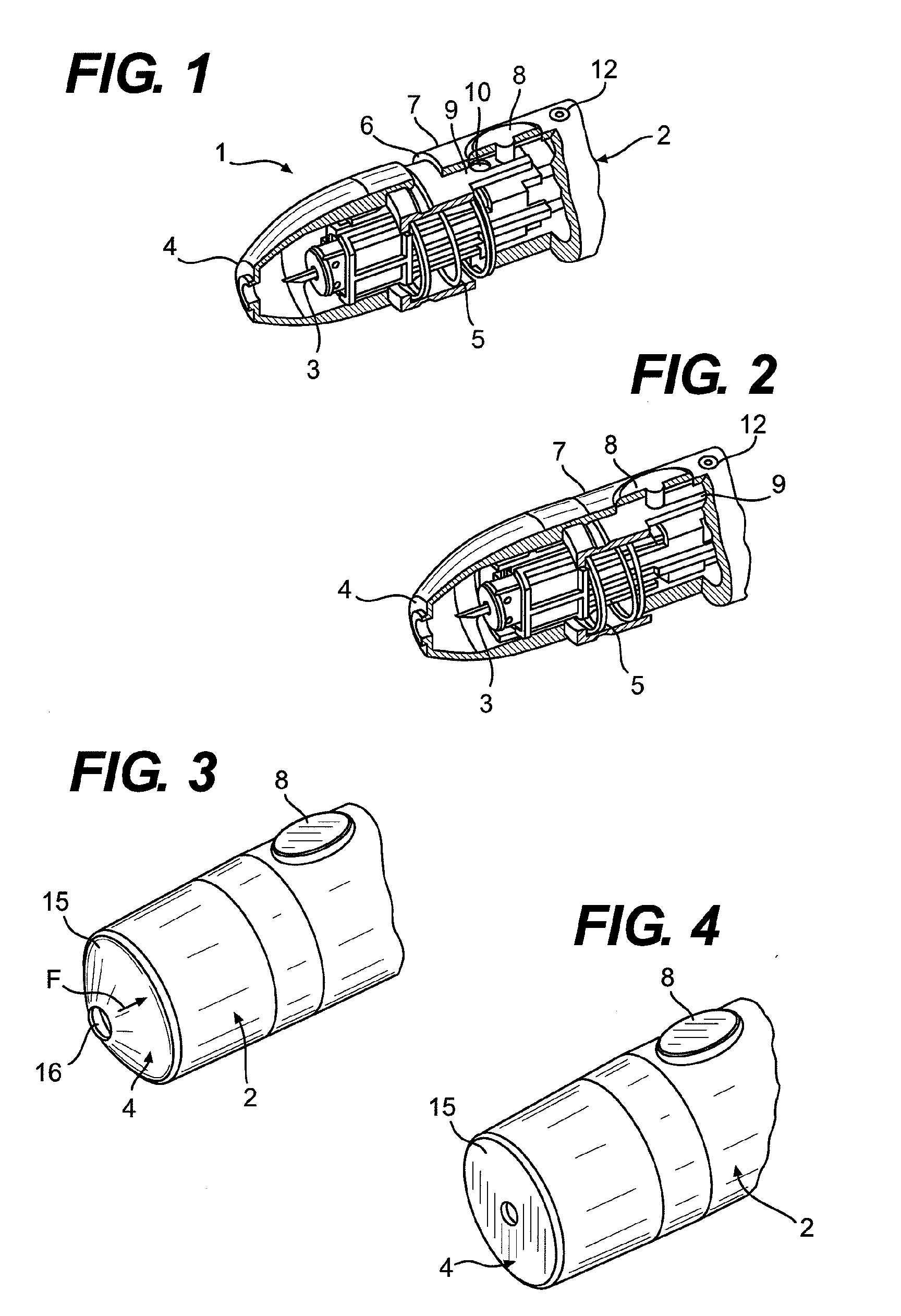
[0036]The puncturing system 1 shown in FIG. 1 comprises a puncturing device 2 and puncturing elements 3 that are intended for single use and are to be inserted in the puncturing device 2. In order to generate a puncture wound, the press-on part 4 of the puncturing device 2 is pressed against a skin surface of a user. If the pressure that is exerted in the process exceeds a minimum pressure that is defined by the strength of a spring 5, the press-on part 4 is pushed against an edge 6 of the device housing 7.

[0037]The puncturing device 2 shown has a triggering means 8 by actuation of which a user can trigger a puncturing motion aft...


PUM


Abstract

The invention relates to a puncturing system for generating a puncture wound for obtaining a sample of a body fluid, comprising a press-on part to be pressed onto a body part in which a puncture wound is to be generated, a triggering means, by the actuation of which a user can trigger a puncturing motion of a puncturing element after the press-on part is pressed on, and a testing facility for determining at least one test parameter on which a sample-obtaining probability depends. A securing facility is also provided that, in a locked state, locks the triggering means such that no puncturing motion can be triggered, and, in a triggering state, releases the triggering means such that a puncturing motion can be triggered by actuation thereof, whereby the securing facility is transitioned from the locked state to the triggering state by the testing facility when the test parameter determined by the testing facility meets defined minimum requirements. A signaling facility is also provided for signaling a transition of the securing facility to the triggering state and / or for signaling that the securing facility is in the triggering state. The invention also relates to a method for preparing a puncturing system for generating a puncture wound.

Description

[0001]This application is a continuation application of International Application PCT / EP2006 / 009257, filed Sep. 23, 2006, which claims priority to EP 05 021 983.1, filed Oct. 8, 2005, which are hereby incorporated by reference in their entirety.BACKGROUND[0002]The invention relates to a puncturing system for generating a puncture wound for obtaining a sample of a body fluid. The body fluid is typically blood, but in some cases may be interstitial fluid. Reference shall be made hereinafter to blood as an example of body fluids, recognizing that fluids other than blood can be obtained from a puncture wound.[0003]Puncturing systems (lancing devices) of this type usually consist of disposable puncturing elements that are designed for single use for puncturing the skin and a puncturing device having a drive for the puncturing motion of the puncturing element. The puncturing device of a puncturing system of this type has a press-on part to be pressed onto the body part in which a puncture...

Claims


Application Information

Patent Timeline
IPC IPC(8): A61B5/00
CPCA61B5/1411A61B5/14532A61B5/150022A61B5/150068A61B5/150412A61B5/150503A61B5/150824A61B5/150954A61B5/15113A61B5/1519
Inventor LIST, HANSHOERAUF, CHRISTIANDECK, FRANKWEISS, THOMASKISTNER, MICHAELSCHMELZEISEN-REDEKER, GUENTHERFRUHSTORFER, HEINRICHHAAR, HANS-PETERKRAEMER, UWEHOENES, JOACHIMMILTNER, KARL
Owner ROCHE DIABETES CARE INC
Learn More