Energy Harvester for an Implant Device

a technology of energy harvester and implant device, which is applied in the direction of mechanical energy handling, dynamo-electric components, electrical apparatus, etc., can solve the problems of affecting the life span of the device, the limiting factor of current battery technology, and the marginal increase in the storage capacity to volume ratio of the devi

Inactive Publication Date: 2008-10-23
PERPETUUM
View PDF17 Cites 33 Cited by
  • Summary
  • Abstract
  • Description
  • Claims
  • Application Information

AI Technical Summary

Benefits of technology

[0046]In a particularly preferred embodiment, the present invention relates to the use of an electromagnetic generator and a pressure bladder located within a biological living body, in a particular a mammal, such as the human body, in such a position to take advantage of the pressure fluctuations

Problems solved by technology

However, current battery technology is the principal limiting factor to the life span of these devices, as battery capacity has reached a plateau, with recent developments in battery technology producing only marginal increases in storage capacity to volume ratios.
Not only is this time consuming for the patient, but is also inefficient in its power use, as a large proportion of the energy used to power the induction loop is lost due to heating and magnetic field fringe effects.
Inefficienc

Method used


Image

  • Energy Harvester for an Implant Device
  • Energy Harvester for an Implant Device
  • Energy Harvester for an Implant Device

Examples


Embodiment Construction

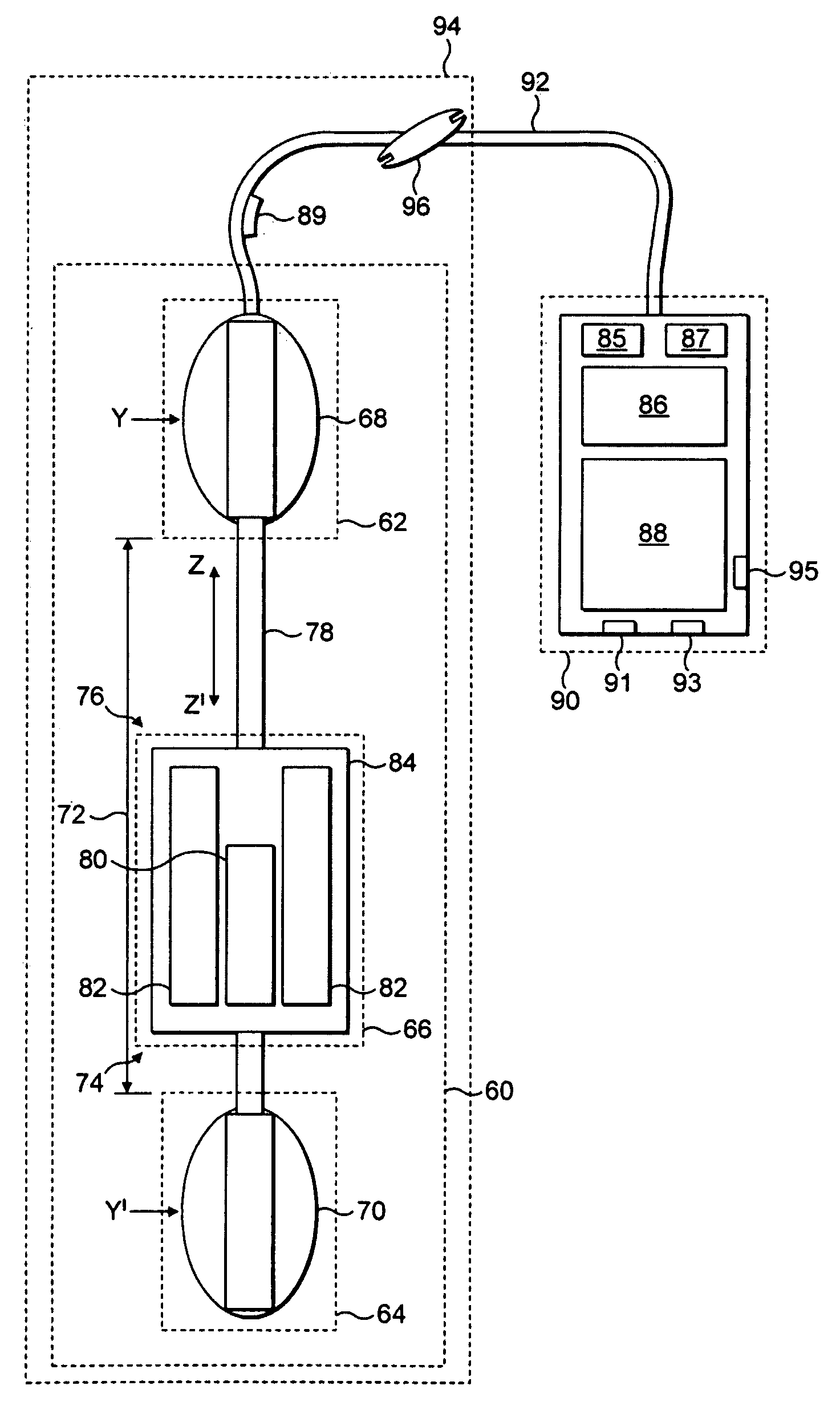
[0052]Referring to FIG. 1, there is shown schematically an energy harvester implant device in accordance with a first preferred embodiment of the present invention when implanted into the human body.

[0053]The energy harvester implant device, designated generally as 2, comprises a pressure responsive device 4 containing a working fluid coupled to an electrical generator 6 which converts pressure changes in the working fluid into electrical energy. In use, the energy harvester implant device 2 is implanted into the living body so that the pressure responsive device 4 is subjected to pressure fluctuations within the living body, and in particular to blood pressure fluctuations found within the blood circulatory system.

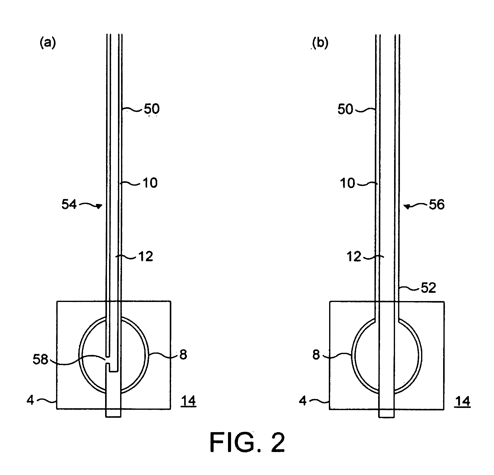
[0054]The pressure responsive device 4 comprises a deformable pressure bladder 8 and a pressure transmission conduit 10. The pressure responsive device 4 is a hydraulic or pneumatic device, and is filled with a pressure transmitting working fluid 12 which is a biologicall...


PUM


Abstract

This invention relates to the use of an electromagnetic generator and a pressure bladder located within a biological body in such a position to take advantage of the pressure fluctuations found within that body to produce electrical power. The invention uses these pressure fluctuations to displace the moving parts of a generator, to produce electricity in accordance with the Faraday principal, to power implanted devices.

Description

BACKGROUND OF THE INVENTION[0001]1. Field of the Invention[0002]The present invention relates generally an energy harvester for an implant device and to an implant device including such an energy harvester. The present invention also relates to an implant apparatus for implantation into a mammal, a method of implanting an implant apparatus into a mammal and a method of operating an implant apparatus that is implanted into a mammal. In particular, the present invention relates generally to the field of power generation within a biological living body, such as a mammal, using motions of that body to produce electrical energy, to power a variety of types of implant devices.[0003]2. Description of the Prior Art[0004]Current medical implant devices, such as pacemakers and defibrillators, rely heavily on electrical power to function for extended periods of time. However, current battery technology is the principal limiting factor to the life span of these devices, as battery capacity has ...

Claims


Application Information

Patent Timeline
IPC IPC(8): A61N1/362H02K35/00
CPCA61N1/36557H02K7/1876A61N1/3785A61N1/36564
Inventor ROBERTS, STEPHENFREELAND, ROYSTANLEY, GILESDAWKINS, KEITH DOBSONMORGAN, JOHN MARKROBERTS, PAUL R.
Owner PERPETUUM
Why Eureka
Try Eureka