Charge/discharge control apparatus for hybrid vehicle and control program device therefor

a control apparatus and hybrid technology, applied in the direction of electric devices, process and machine control, propulsion using engine-driven generators, etc., can solve the problems of reducing the traveling performance of the vehicle, difficult to realize the target amount of electric power remaining in the battery, and difficult to reduce pollution or save energy

Active Publication Date: 2008-10-23
DENSO CORP
View PDF7 Cites 121 Cited by
  • Summary
  • Abstract
  • Description
  • Claims
  • Application Information

AI Technical Summary

Benefits of technology

[0007]It is an object of the present invention to provide a charge/discharge control apparatus for a hybrid vehicle that controls in a simplified manner electric power consumption of a battery up to a charge-possible poi...

Problems solved by technology

This makes it difficult to lower the pollution or to save energy.
Besides, this decreases the traveling performance of the vehicle.
However, it is difficult to realize the target amounts of electric power remaining in the battery by the above technology.
Control processing becomes...

Method used


Image

  • Charge/discharge control apparatus for hybrid vehicle and control program device therefor
  • Charge/discharge control apparatus for hybrid vehicle and control program device therefor
  • Charge/discharge control apparatus for hybrid vehicle and control program device therefor

Examples


first embodiment

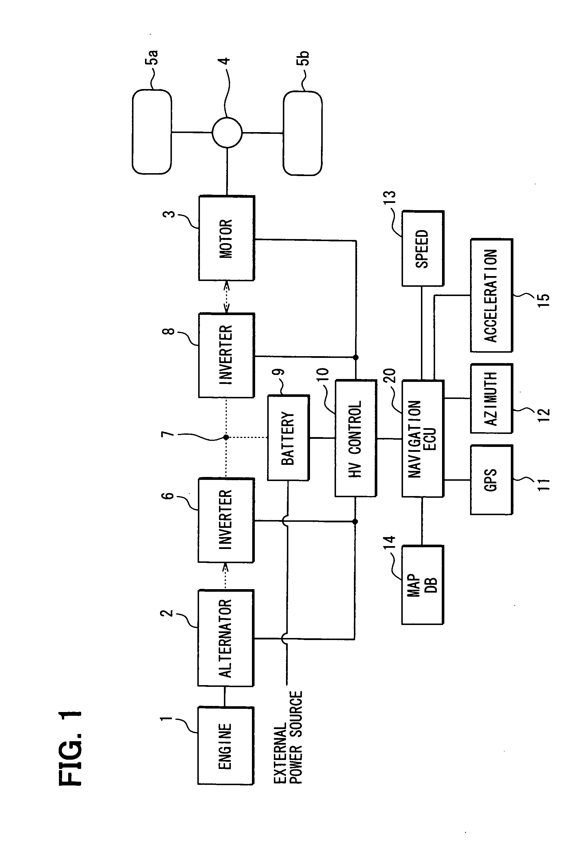
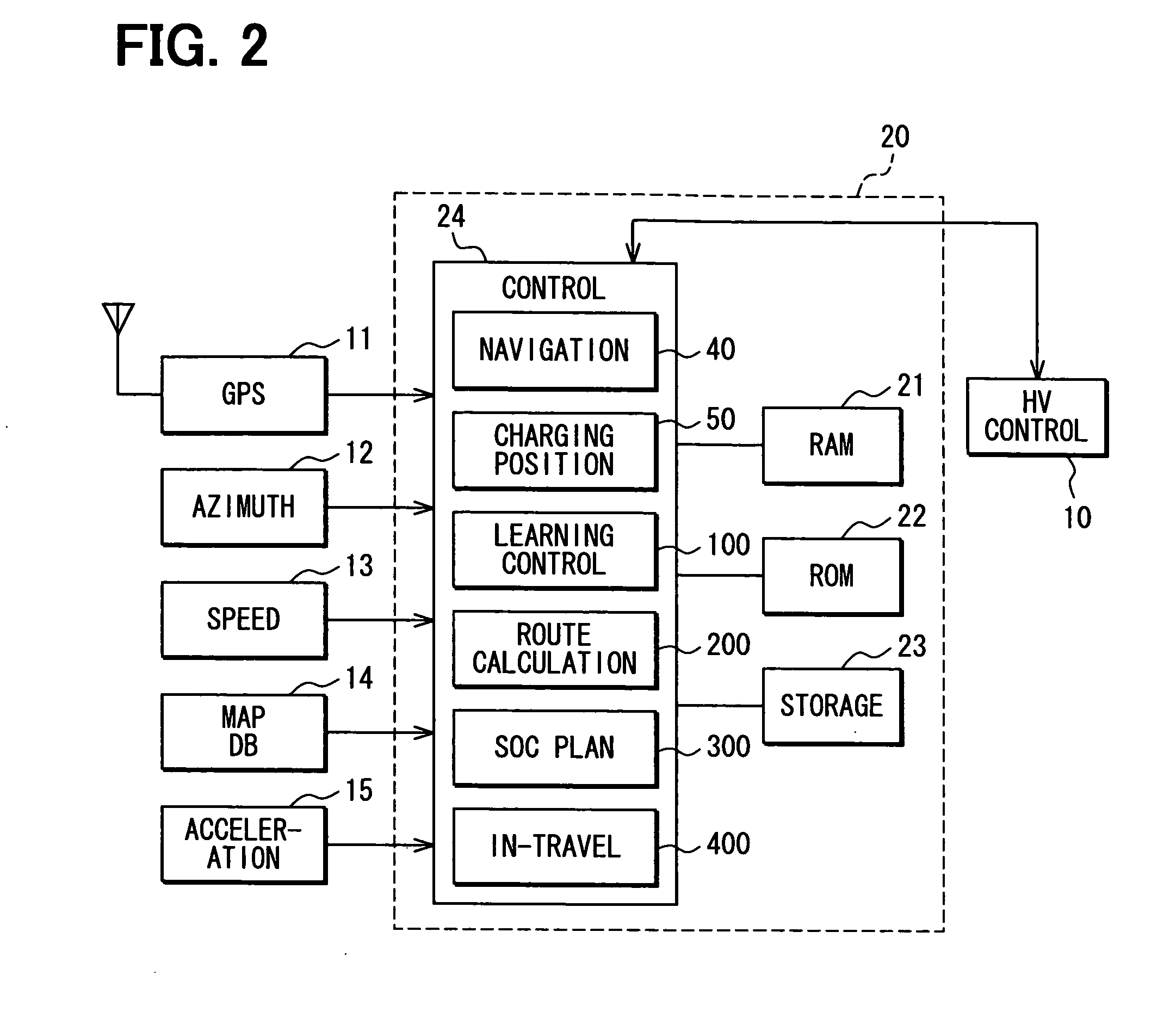
[0022]Referring first to FIG. 1, a hybrid vehicle has an internal combustion engine 1, an alternator 2, an electric motor 3, a differential gear 4, tires 5a, 5b, an inverter 6, a DC link 7, an inverter 8, a battery 9, an HV control unit 10, a GPS sensor 11, an azimuth sensor 12, a vehicle speed sensor 13, a map DB storage unit 14, an acceleration sensor 15 and a navigation ECU 20.

[0023]The hybrid vehicle travels using the engine 1 and the electric motor 3 as drive power sources. When the engine 1 is used as the drive power source, the rotational force of the engine 1 is transmitted to the tires 5a, 5b via a clutch mechanism (not shown) and the differential gear 4 in the known manner. When the electric motor 3 is used as the drive power source, the DC power of the battery 9 is converted into the AC power through the DC link 7 and the inverter 8, the electric motor 3 is operated by the AC power, and the rotational force of the electric motor 3 is transmitted to the tires 5a, 5b throug...

second embodiment

[0078]Next, a second embodiment is shown in FIG. 9 and different from the first embodiment with respect to the combination of the EV mode and HV mode. Specifically, in the first embodiment, the traveling mode is the HV mode over the whole sections from the start point up to the commence point of the EV finish section on the optimum route up to the destination point. In the second embodiment, as shown in FIG. 9, the traveling mode is the EV mode from a start point 91 up to a given point (end point) 92 among the sections from the start point 91 up to a commence point 93 of the EV finish section, and the traveling mode is the HV mode from the end point 92 up to the commence point 93 of the EV finish section.

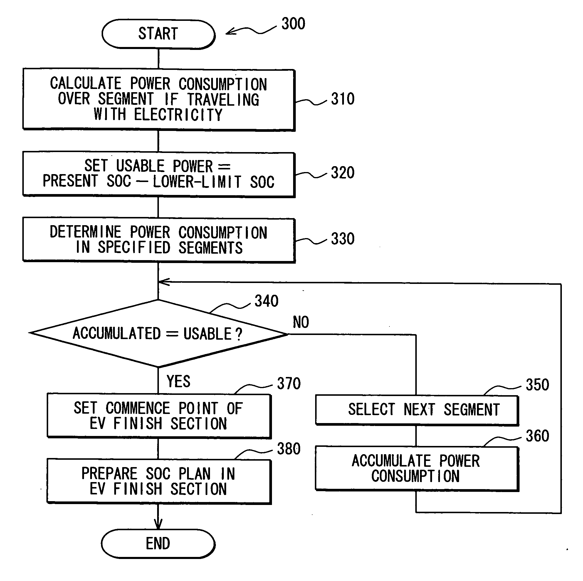
[0079]To realize the above operation, the control unit 24 in the SOC management plan preparation processing 300 calculates the amount of battery power consumption when the EV mode is used over a section continuing along the optimum route from the start point 91 on the optimum route ...

third embodiment

[0084]Next, a third embodiment is shown in FIGS. 10 and 11. This embodiment is different from the first embodiment in that the control unit 24 in executes an in-travel processing 4000 shown in FIG. 10 instead of the in-travel processing 400 (FIG. 8). The in-travel processing 4000 is different from the in-travel processing 400 in that an exception processing of step 455 is executed between step 454 and step 460. The exception processing is for checking whether it has become necessary to change the SOC management plan and for preparing the SOC management plan again if it has become necessary.

[0085]In the exception processing 455 shown in FIG. 11, the control unit 24, first, compares at step 530 the present SOC received just before with the target SOC corresponding to the present position and checks whether the difference is larger than a reference width or, more closely, whether the present SOC is smaller than the target SOC by more than a reference width R. If the check result is aff...


PUM


Abstract

A navigation ECU records a charge-possible point through charging position record processing and records the history of traveling conditions near the charge-possible point through learning control processing. If a destination point on an optimum route is the charge-possible point, the navigation ECU determines a continuous section where the EV traveling is possible up to the charge-possible point based on the history through SOC management plan preparation processing, and changes over the HV traveling and the EV traveling according to the determination through in-travel processing.

Description

CROSS REFERENCE TO RELATED APPLICATION[0001]This application is based on and incorporates herein by reference Japanese Patent Application No. 2007-112756 filed on Apr. 23, 2007.FIELD OF THE INVENTION[0002]This invention relates to a charge / discharge control apparatus for a hybrid vehicle and to a control program device for the charge / discharge control apparatus.BACKGROUND OF THE INVENTION[0003]A hybrid vehicle such as a plug-in hybrid vehicle is equipped with a battery as well as an internal combustion engine and an electric motor as power sources for traveling. The battery supplies electric power to the electric motor and is electrically charged with electric power from an external power source.[0004]In this type of hybrid vehicles, it is desired that the electric power remaining in the battery is consumed to its lower-limit value at the time when the battery is to be charged next time from an external power source so as to lower the pollution and to save energy. On the other hand,...

Claims


Application Information

Patent Timeline
IPC IPC(8): B60W10/26B60W20/00B60L50/15B60L50/16
CPCB60K6/46Y02T10/7241B60L11/123B60L11/1816B60L11/1861B60L2210/40B60L2240/12B60L2240/62B60L2240/622B60L2240/64B60L2240/642B60L2240/645B60L2260/54B60W10/06B60W10/08B60W10/26B60W20/00B60W2550/141B60W2550/143B60W2550/402Y02T10/6217Y02T10/6286Y02T10/7005Y02T10/7044Y02T10/705Y02T10/7077Y02T10/7291Y02T90/127Y02T90/14Y02T90/16Y02T90/162B60L3/12B60L50/61B60L53/14B60L58/12B60W2552/05B60W2552/20B60W2556/50Y02T10/62Y02T10/70Y02T10/7072Y02T10/72B60W20/13Y02T90/12
Inventor YAMADA, KAZUNAO
Owner DENSO CORP
Why Eureka
Try Eureka