
Computer system and communication control method

a computer system and communication control technology, applied in computing, instruments, electric digital data processing, etc., can solve the problems of not making an achievement regarding reliability and cpu-load reduction, and no achievement is made regarding the control of the communication path in which consideration is given to communication reliability, so as to reduce the cpu usage ratio used

Inactive Publication Date: 2008-10-23
HITACHI LTD
View PDF4 Cites 28 Cited by
  • Summary
  • Abstract
  • Description
  • Claims
  • Application Information

AI Technical Summary

Benefits of technology

[0011]It is an object of the present invention to provide a technology for implementing a reduction in the CPU usage ratio in the network processing between operating virtual machines, and for dynamically controlling the multiplicity degree of a multiplexed communication path.
[0012]Also, it is another object of the present invention to ensure reliability for preventing such phenomena as loss of information on the communication path, including a physical communication path.
[0017]For example, in the present invention, a virtual machine-real machine pair information table is provided within a memory of a real machine. When an application operating in a virtual machine within the real machine makes a communication request, the application makes the communication request to a multiplicity-degree control function existing in the virtual machine. The multiplicity-degree control function makes reference to the virtual machine-real machine pair information table, thereby making the judgment as to whether or not a communication-destination virtual machine exists on the same real machine as that of the communication-source virtual machine. If the communication-destination virtual machine exists on the same real machine, the multiplicity degree of the multiplexed communication path is lowered, thereby reducing the CPU usage ratio of the real machine needed for the network processing.
[0019]According to the present invention, it becomes possible to ensure the communication reliability, and to reduce the CPU usage ratio used for the network processing.
[0020]Also, according to the present invention, it becomes possible to prevent such phenomena as loss of information, thereby allowing accomplishment of the ensuring of the reliability.

Problems solved by technology

Namely, no accomplishment is made regarding the implementation of reliability and CPU-load reduction by dynamically changing the communication path through consideration of position relationship between the communication-destination virtual machine and the communication-source virtual machine.
In the virtual network, however, no accomplishment is made regarding the control over the communication path in which consideration is given to the communication reliability and attention is paid to the existence of the communication-destination virtual server.

Method used


Image

  • Computer system and communication control method
  • Computer system and communication control method
  • Computer system and communication control method

Examples


1st embodiment

[0037]Hereinafter, referring to FIG. 1 through FIG. 5, the explanation will be given below concerning a first embodiment.

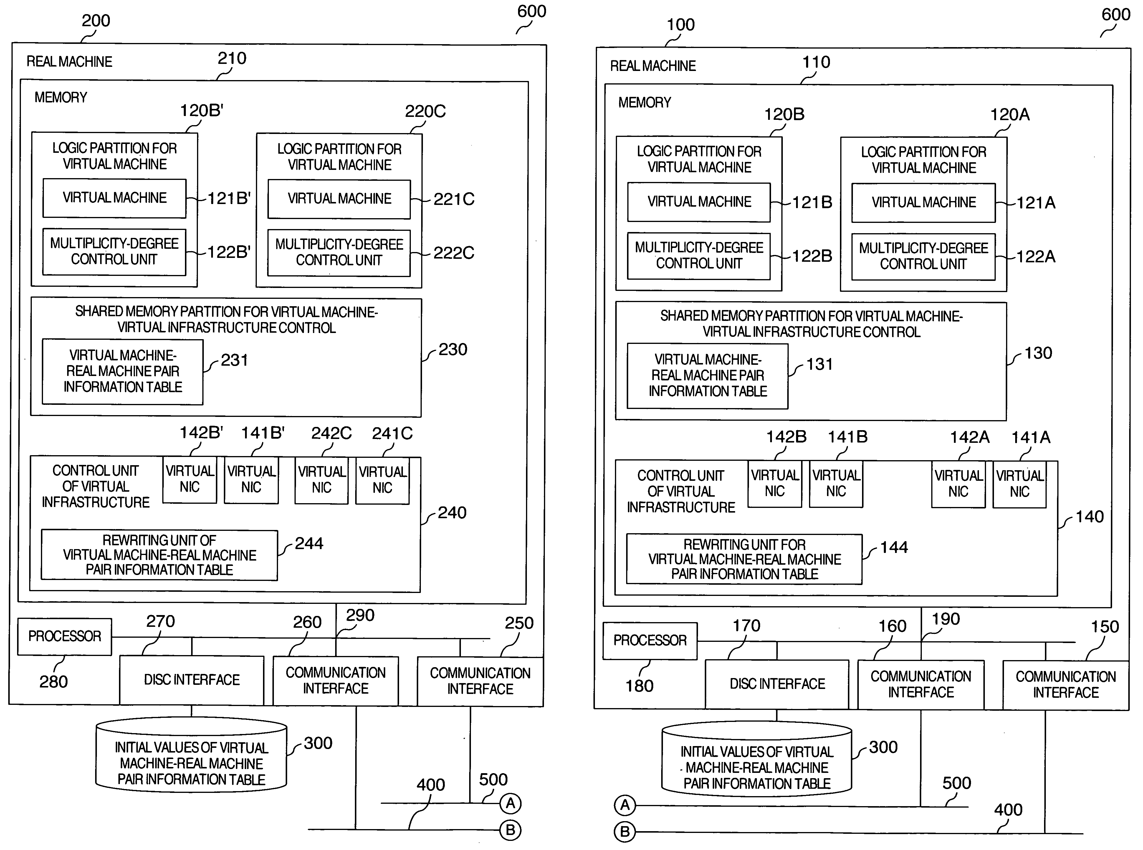
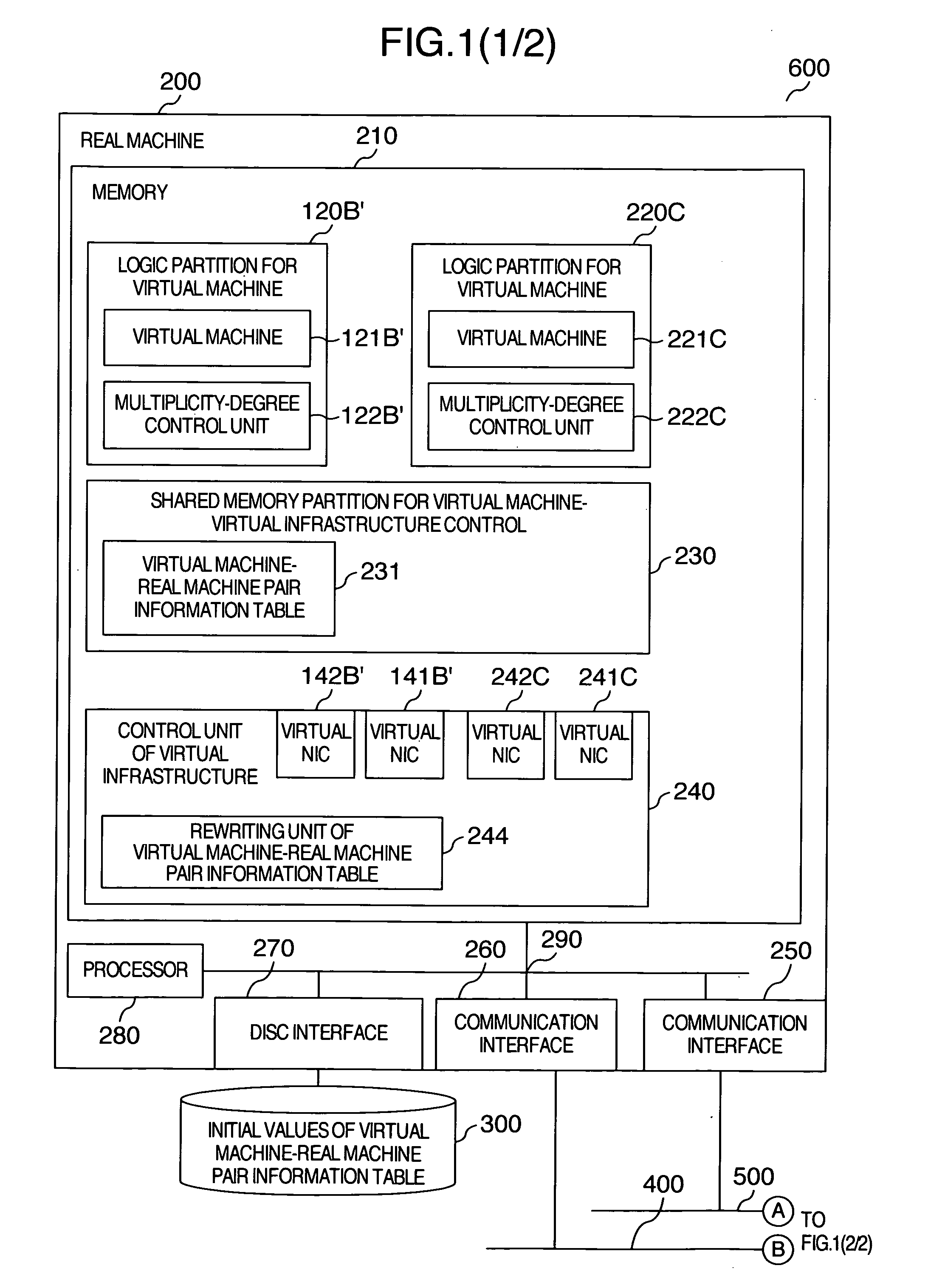
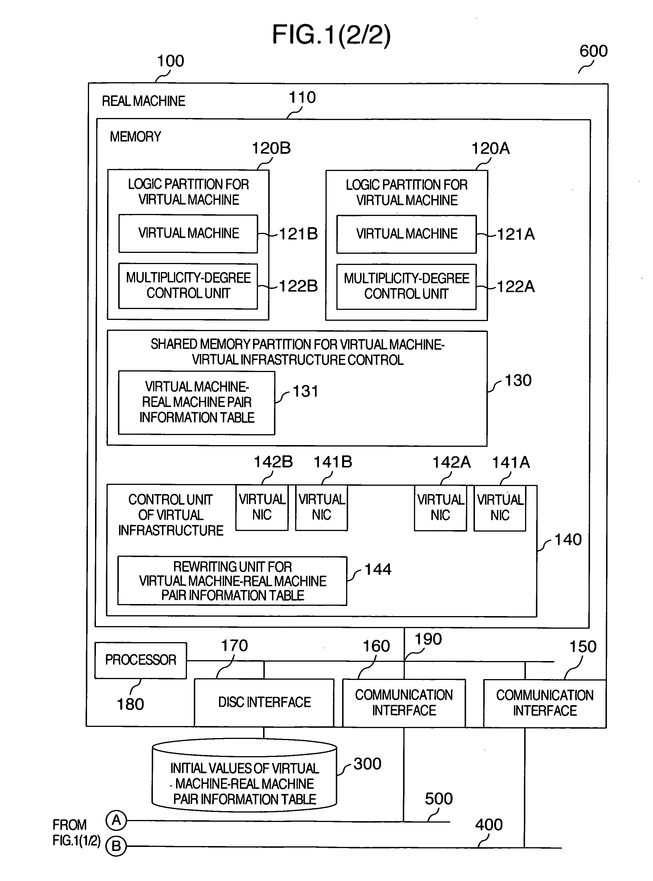
[0038]FIG. 1 is a configuration of the present embodiment. A communication-path control system 600 includes a first real machine 100 and a second real machine 200. These real machines are connected via LANs 400 and 500, and implement duplexed multiplicity degree.

[0039]The first real machine 100 is a configuration example of the real machine which operates a virtual machine. The first real machine 100 includes a processor 180, a memory 110, communication interfaces 150 and 160, and a disc interface 170. These devices are connected via a communication path 190. Here, a bus will be used for the explanation concretely.

[0040]The first real machine 100 has, outside the machine, a disc 300 which records initial values of virtual machine-real machine pair information table. Also, network cables 400 and 500 used for the multiplexing are connected to the communication inter...

2nd embodiment

[0062]Hereinafter, referring to FIG. 1 and FIG. 6 through FIG. 8, the explanation will be given below concerning a second embodiment.

[0063]The present embodiment indicates the multiplexing of a communication path in a case where the logical partition 120B for virtual machine will be displaced from the real machine 100 to the real machine 200.

[0064]In FIG. 1, the logical partition 120B for virtualmachine, which has existed on the memory 110 of the real machine 100, will be displaced onto the memory 210 of the real machine 200 (i.e., the logical partition 120B′ for virtual machine). Also, the virtual NIC processing units 141B and 142B exist on the control unit 240 of virtual infrastructure as the identical processing units to the ones before the displacement from the real machine 100 (i.e., 141B′ and 142B′).

[0065]Incidentally, the logical partition 220C for virtual machine on the real machine 200 in FIG. 1 will not be used in the present embodiment.

[0066]FIG. 6 is an example for illus...

3rd embodiment

[0072]Hereinafter, referring to FIG. 9 through FIG. 13, the explanation will be given below concerning a third embodiment.

[0073]FIG. 9 is a configuration of the present embodiment. The communication-path control system 600 includes the first real machine 100 and the second real machine 200. These real machines are connected via a LAN 400, and implement uniplexed multiplicity degree.

[0074]The first real machine 100 is a configuration example of the real machine which operates a virtual machine. The first real machine 100 includes the processor 180, the memory 110, the communication interfaces 150 and 160, and the disc interface 170. These devices are connected via the communication path 190. Here, a bus will be used for the explanation concretely.

[0075]The first real machine 100 is connected in a communication-capable manner to the disc 300 which records initial values of virtual machine-real machine pair information table. On the present table, the correspondence relationship is ind...


PUM


Abstract

A technology is provided, in which pair information of a virtual machine and a real machine on which the virtual machine operates are made related with each other, and are recorded into a shared memory partition of the virtual machine and a control function of virtual machine infrastructure, from the above-described recorded information, a judgment is made as to whether or not a communication-destination virtual machine exists on the same real machine as that of a communication-source virtual machine, and a technology for changing the multiplicity degree in accordance with this judgment, moreover, the above-described recorded information is written when the virtual machine has displaced to another real machine to implement a reduction in the CPU usage ratio in network processing between the operating virtual machines, and to dynamically control the multiplicity degree of the communication path by making full use of location information between the virtual machines.

Description

INCORPORATION BY REFERENCE[0001]The present application claims priority from Japanese application JP-2007-096006 filed on Apr. 2, 2007, the content of which is hereby incorporated by reference into this applicationBACKGROUND OF THE INVENTION[0002]1. Field of the Invention[0003]The present invention relates to a method of controlling a communication path between a client's virtual machine and a server's virtual machine which operate by taking advantage of control function of virtual infrastructure.[0004]2. Description of the Related Art[0005]Conventionally, a client and a server had been constructed in real machines respectively, and the communication path had been established between the real machines by using a real network. Moreover, in order to enhance reliability in the communication, such technologies as teaming for duplexing the communication path have been developed intensively and enthusiastically. At present, a virtual machine can be set up on a real machine by taking advan...

Claims


Application Information

Patent Timeline
Patent Type & Authority Applications(United States)
IPC IPC(8): G06F9/455
CPCG06F9/45533G06F9/5077G06F9/45558G06F2009/45595
Inventor AMANO, KOJIOHIRA, TAKAHIRO
Owner HITACHI LTD
Learn More