
Reinforcing Assemblies and Reinforced Concrete Structures

a technology of reinforced concrete and assemblies, applied in the direction of building reinforcements, construction, building material handling, etc., can solve the problems of structural failure, undesirable cracking and/or breaking of structural concrete members, structural failure, etc., to achieve better anchorage, reduce structural concrete failure, and eliminate or minimize structural concrete failure

Inactive Publication Date: 2008-10-30
P T E STRAND CO
View PDF6 Cites 24 Cited by
  • Summary
  • Abstract
  • Description
  • Claims
  • Application Information

AI Technical Summary

Benefits of technology

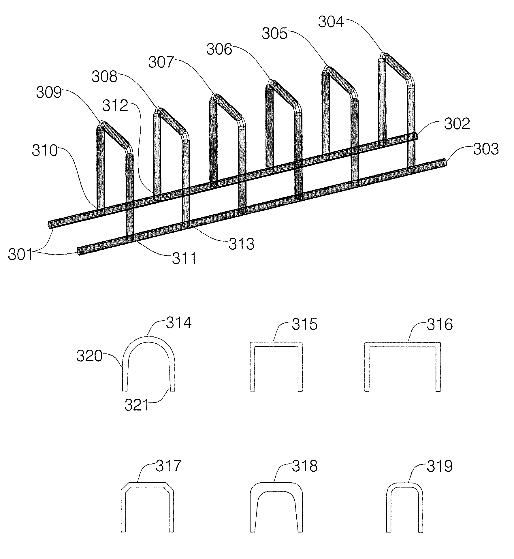
[0006]The reinforcing assembly of the present invention involves a support base that comprises two elongate rebar members disposed substantially parallel to each other, and several shear-resisting rebar elements having two opposing ends and a hairpin shape on a common plane in generally parallel orientation to each other and secured to the base. The rebar elements may be cast in the hairpin shape, or they may be reformed by bending; and they may have a smooth surface, which affords cost savings, or be ribbed or corrugated in order to improve cohesion between the steel and the concrete. The reinforcing assemblies of the present invention are best used as sets of four units that are strategically placed at or near the areas of high shear failure propensity. The reinforced concrete structure of the invention includes a concrete member, having a first face and a generally opposed second face, and at least four reinforcing assemblies that are embedded and mechanically retained in a prescribed location within the concrete member by their base and by the opposed faces of the concrete member. Each of the four reinforcing assemblies of the reinforced concrete structure comprises a support base and multiple hairpin-shaped rebar elements secured to the support base.

Problems solved by technology

While concrete made in this fashion, usually referred to as “unreinforced concrete”, has fairly good resistance to compressive stresses, any significant tension will tend to break the rigid structure and cause undesirable cracking and separation of the concrete.
Commercial and industrial structural concrete members such as slabs, beams, footings and flat foundations, even when made with reinforced concrete, are susceptible to shear forces that create tensile forces along them and often result in structural failure, that is, undesirable cracking and / or breaking of the structural concrete members.
The type of failure caused by these shear forces and the attendant incline cracks that tend to propagate throughout the concrete, usually from the area under tension towards the area under compression, are not always easy to detect and correct since they are often not visible when they occur.
Two-way shear failure, often referred to as “punching shear failure”, tends to occur in horizontal concrete members such as slabs, footings and flat foundations.
Post-tensioned slabs and slabs that make use of high-strength concrete are particularly susceptible to punching shear failure.
Conventional solutions to shear problems are not always satisfactory when dealing with punching shear problems.
Stirrups, with longitudinal bars or with vertical bars, are difficult to place in the concrete structures and often present anchorage slip problems.
Increasing the strength of concrete slabs with conventional stirrups is common, but the anchorage of stirrups is difficult to provide in thin slabs (e.g., less than about 6 inches in height) and therefore should be used only if the stirrups are closed and contain a longitudinal bar at each corner.
Shearheads are rarely used because their installation is very expensive and because they often interfere with the placement of flexural reinforcing bars and post-tensioned cables.
Also, because of their anchor heads, studrails do not always provide adequate confinement of the concrete where the punching shear failure tends to occur.

Method used


Image

  • Reinforcing Assemblies and Reinforced Concrete Structures
  • Reinforcing Assemblies and Reinforced Concrete Structures
  • Reinforcing Assemblies and Reinforced Concrete Structures

Examples


Embodiment Construction

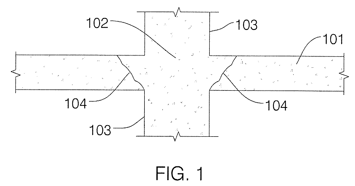
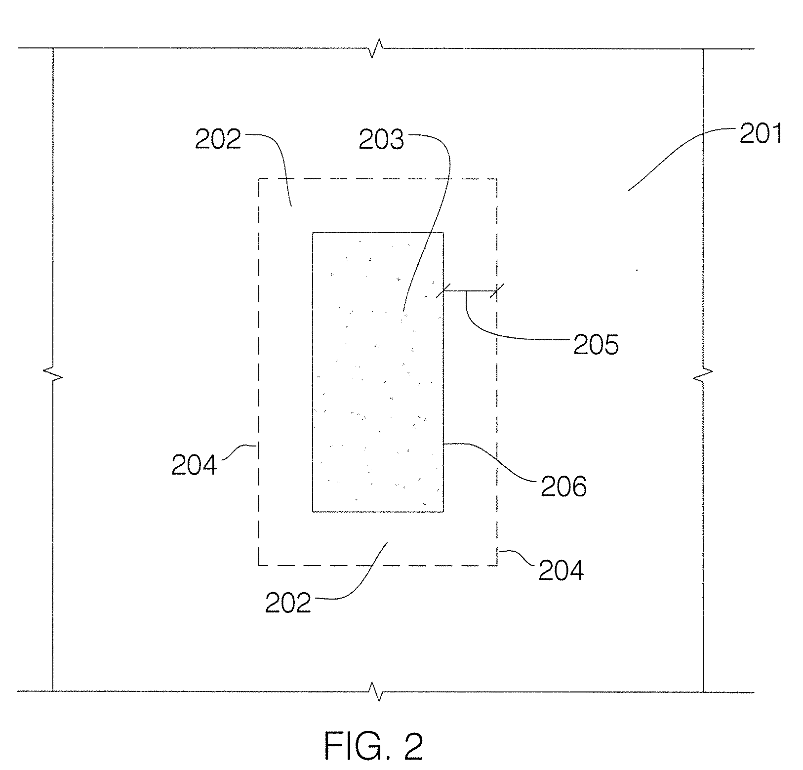
[0016]The invention will now be described with reference to its application to a post-tensioned slab structure that is supported by a column, which may be a steel supporting column or a concrete supporting column. FIG. 1 represents a cross-sectional view of a concrete slab structure 101 at the “loaded” area 102 (also referred to as the “reaction” area) surrounding the intersection of the slab structure with concrete supporting column 103, and showing undesirable cracking 104 caused by punching shear forces. This is a typical two-way shear situation. FIG. 2 is a top view of the concrete slab structure depicted in FIG. 1 and shows post-tensioned concrete slab 201 (slab 101 in FIG. 1) intersected by concrete supporting column 203 (column 103 in FIG. 1) and creating loaded, or reaction, area 202 delineated by shear critical section perimeter 204. The maximum distance 205 at which the American Concrete Institute (“ACI”) requires any reinforcing assembly to be located inside a concrete sl...


PUM


Abstract

Reinforcing assemblies for use in structural concrete members, as well as reinforced concrete structures, are provided that are uniquely suited to deal with punching shear failure in structural concrete members such as slabs, beams footings and flat foundations. The reinforcing assemblies include a support base, comprising two elongate rebar members disposed substantially parallel to each other, and several shear-resisting rebar elements having two opposing ends and cast, or bent, in hairpin shape on a common plane in generally parallel orientation to each other and secured to the base. The reinforced concrete structures include a concrete member, having a first face and a generally opposed second face, and at least four reinforcing assemblies that are embedded and retained at prescribed locations within the concrete member by their base and by the opposed faces of the concrete member, and which comprise a support base and multiple hairpin-shaped rebar elements secured to the support base.

Description

FIELD OF THE INVENTION[0001]This invention relates to reinforcing assemblies for use in structural concrete members. In particular, this invention is concerned with a reinforcing system that is uniquely suited to deal with shear failure and with punching shear failure in structural concrete members such as slabs, beams, footings and flat foundations. More particularly, the invention relates to a structural concrete reinforcing assembly that may be made entirely of rebar. Specifically, the invention relates to a novel technique for eliminating or minimizing shear failure and punching shear failure in structural concrete members such as slabs, beams, footings and flat foundations by means of a unique reinforcing assembly made up of hairpin-shaped rebars, which novel technique allows the user to fabricate reinforced concrete structures with enhanced punching-shear-resistant capabilities.BACKGROUND OF THE INVENTION[0002]Commercial concrete is a mixture of cement, sand and stone aggregat...

Claims


Application Information

Patent Timeline
IPC IPC(8): E04C5/06E04C5/01
CPCE04C5/06E04C5/0645
Inventor ABOU-SALEH, ZAHER ALI
Owner P T E STRAND CO
Learn More