Coolant flow swirler for a rocket engine

a technology of rocket engine and swirler, which is applied in the field of cooling system, can solve the problems of limit the amount of power or thrust, and achieve the effects of increasing the temperature of coolant, enhancing convective thermal transfer, and enhancing the cooling of the chamber walls

Inactive Publication Date: 2008-10-30
ROCKETDYNE
View PDF43 Cites 20 Cited by
  • Summary
  • Abstract
  • Description
  • Claims
  • Application Information

AI Technical Summary

Benefits of technology

The present invention is a cooling system for a thrust chamber assembly that improves convective heat transfer. It uses a twisted ribbon/wire to force the coolant to flow in a swirling manner, which breaks up the boundary layer and enhances mixing. This results in improved cooling of the chamber walls, reducing the likelihood of temperature stratification and increasing the material strength capability. The system also allows for more efficient cooling at higher power or oxidizer/fuel mixture ratios, improving the reliability of the engine.

Problems solved by technology

This patent describes a cooling system for a rocket engine's thrust chamber assembly. During operation, the engine produces very hot gas that needs to be cooled down before being released through the nozzle. The current design uses fuel as a coolant by flowing it through small tubes called milled channels, but this method has limited efficiency. Therefore, there is a technical problem of providing an improved cooling system that increases convection-based heat transfer and relies less on fuel consumption.

Method used


Image

  • Coolant flow swirler for a rocket engine
  • Coolant flow swirler for a rocket engine
  • Coolant flow swirler for a rocket engine

Examples


Embodiment Construction

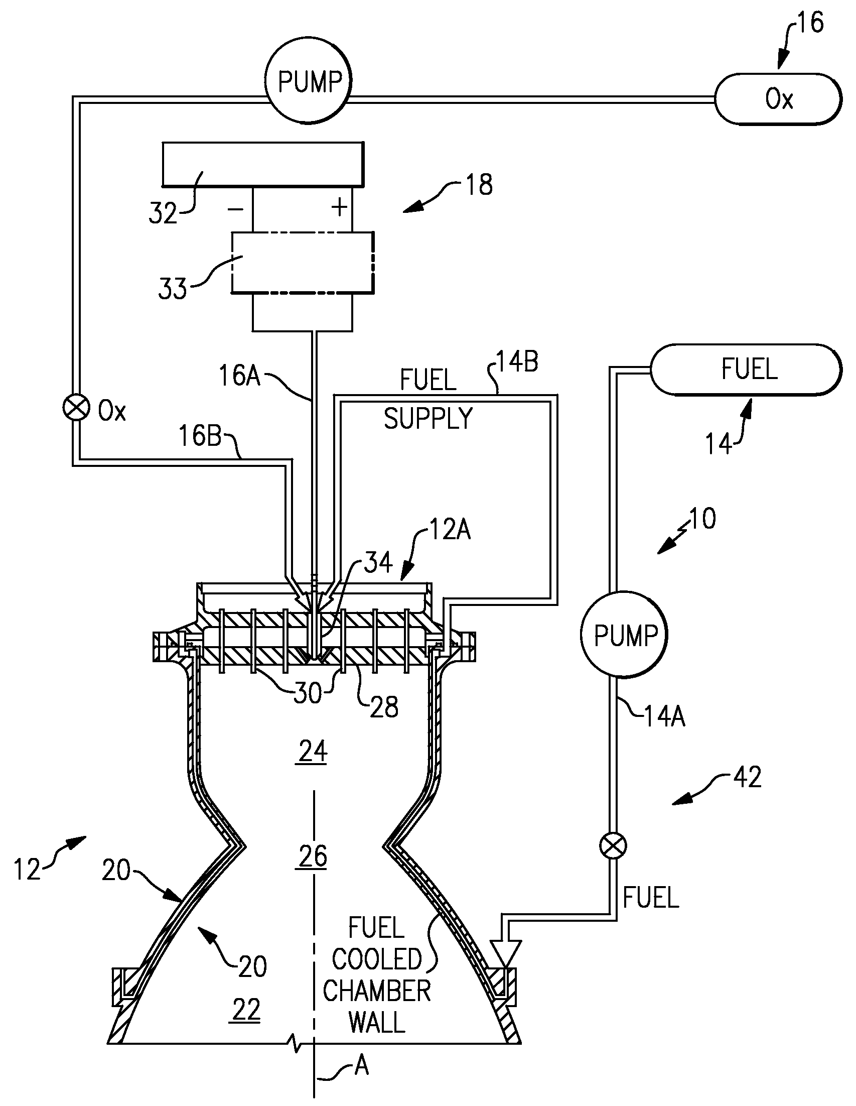
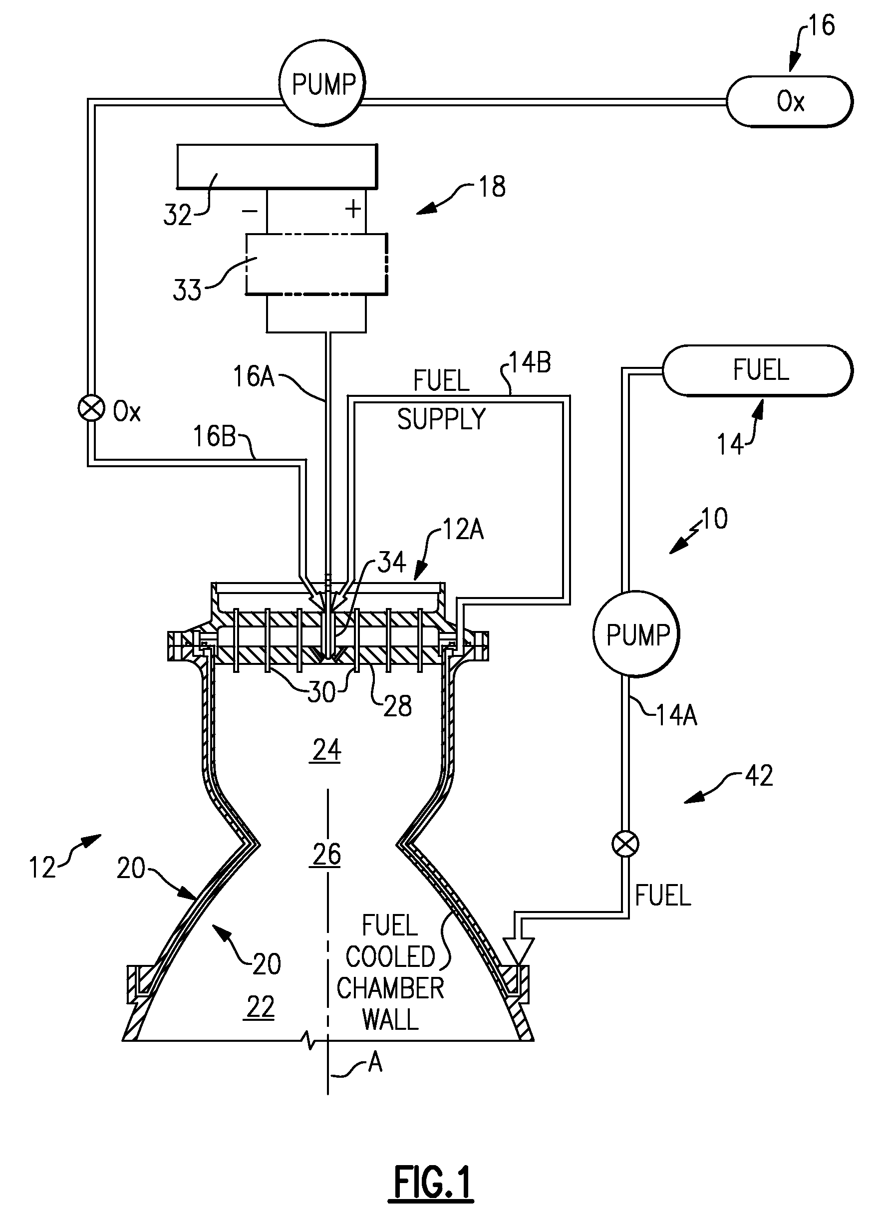
[0016]FIG. 1 illustrates a general schematic view of a rocket engine 10. The engine 10 generally includes a thrust chamber assembly 12, a fuel system 14, an oxidizer system 16 and an ignition system 18. The fuel system 14 and the oxidizer system 16 provide a gaseous propellant system of the rocket engine 10, however, other fluid propellant systems such as liquid will also be usable with the present invention.

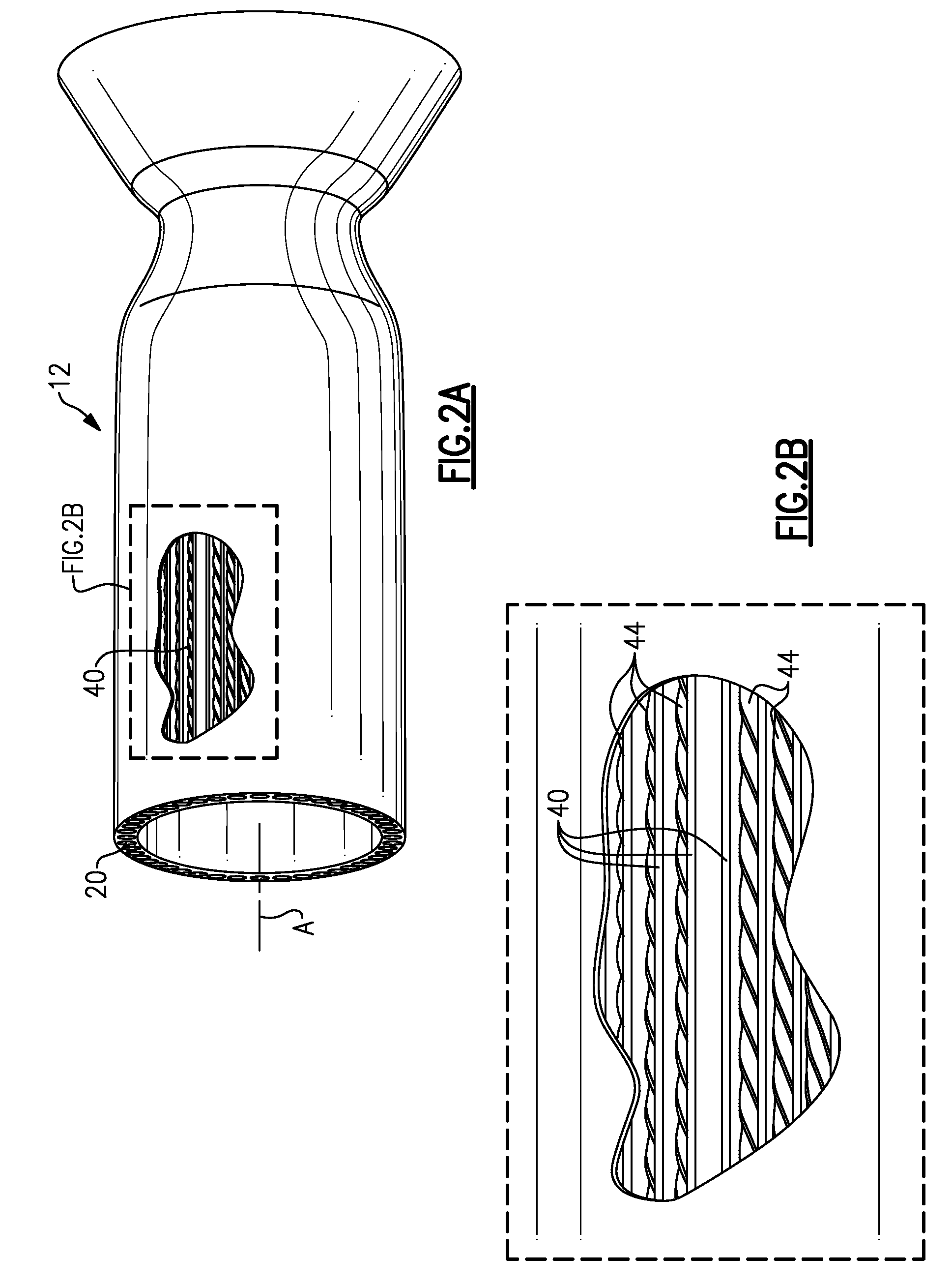
[0017]The thrust chamber assembly 12 is defined by a fluid cooled wall 20 about a thrust axis A. The fluid cooled wall 20 defines a nozzle section 22, a combustion chamber 24 upstream of the nozzle section 22, and a combustion chamber throat 26 therebetween. The thrust chamber assembly 12 includes an injector 12A with an injector face 28 which contains a multitude of fuel / oxidizer injector elements 30 (shown somewhat schematically) which receive fuel which passes first through the fluid cooled wall 20 fed via fuel supply line 14A of the fuel system 14 and an oxidizer such as Gas...


PUM


Abstract

A thrust chamber assembly cooling system includes a twisted ribbon/wire of any one of many variety of cross-sectional shapes located within a nozzle assembly cooling passage to direct the coolant to flow in a swirling manner which induces mixing and breaks up the boundary layer in the coolant passage to enhance the convective heat transfer.

Description


Claims


Application Information

Patent Timeline
Owner ROCKETDYNE
Why Eureka
Try Eureka