Unlock instant, AI-driven research and patent intelligence for your innovation.
Forming mesh
What is Al technical title?
Al technical title is built by PatSnap Al team. It summarizes the technical point description of the patent document.
a mesh and mesh technology, applied in the field of paper machine mesh, can solve the problems of reducing affecting the flatness of the mesh, and carrying a lot of water, so as to reduce the risk of delamination of the two fabric layers, reduce the thickness of the mesh and the disadvantages connected therewith, and the effect of a larger cross-section
Inactive Publication Date: 2008-10-30
VOITH PATENT GMBH
View PDF32 Cites 10 Cited by
Summary
Abstract
Description
Claims
Application Information
AI Technical Summary
This helps you quickly interpret patents by identifying the three key elements:
Problems solved by technology
Method used
Benefits of technology
Benefits of technology
[0021]When weaving with the lower longitudinal threads, the binder threads form segments which extend over two or more consecutive lower longitudinal threads, hence the binder threads extend to a greater extent on the outer side of the lower fabric layer and not between the fabric layers, as the result of which the thickness of the mesh and disadvantages connected therewith are clearly reduced.
[0022]The inventive characteristic that each binder thread weaves over at least two consecutive lower longitudinal threads means furthermore that, when weaving with the lower longitudinal threads, each binder thread extends “flatly” along the outer side of the lower fabric layer and is protected against wear by the lower transverse threads which flank said binder thread on both sides and as a rule have a larger cross-section than the binder threads, thus clearly reducing the risk of delamination of the two fabric layers. Furthermore, within the lower repeat the one of the two flanking lower transverse threads forms respectively one knuckle with the lower longitudinal thread directly preceding the corresponding tie segment and the other of the two flanking lower transverse threads forms respectively one knuckle with the lower longitudinal thread directly following the corresponding tie segment, hence each tie segment of the lower repeat is held firmly in position, thus preventing a relative movement of the binder threads between the lower and upper fabric layer and clearly reducing the inner wear of the mesh resulting therefrom.
[0023]Furthermore, in the lower fabric layer the long floats of the lower transverse threads on the outer side of the lower fabric layer form dewatering channels in regions which extend between two lower transverse threads extending side by side and floating on the outer side. The two flanking lower transverse threads continually cross on the outer side of the lower fabric layer at least the same lower longitudinal threads which together with the binder threads of the pair form the lower segments, hence the cross-sections of the dewatering channels formed by the floats are reduced, thus reducing the otherwise uniform dewatering speed and with it the tendency toward marking.
Problems solved by technology
The known meshes of said kind have the disadvantage that the lower fabric layer is tied at each tie-on point only by way of one warp thread to the upper fabric layer, as the result of which a high force acts on said warp thread and pulls it into the inside of the mesh, thus exerting a negative effect on the flatness of the mesh.
Furthermore, the binder threads on the known meshes of said kind often cover a large distance between the upper and the lower fabric layer, as the result of which the meshes known from the prior art are often very thick and therefore carry a lot of water.
In addition, the meshes known from the prior art often display a dewatering behavior which varies greatly over the mesh surface and can lead to hydraulic marking of the paper formed on such meshes.
Furthermore, on the known meshes the binder threads between the fabric layers are often exposed to high wear because often said threads are not sufficiently fixed between the fabric layers.
Method used
Image
Click on the blue label to locate the original text in one second.
Reading with bidirectional positioning of images and text.
Examples
first embodiment
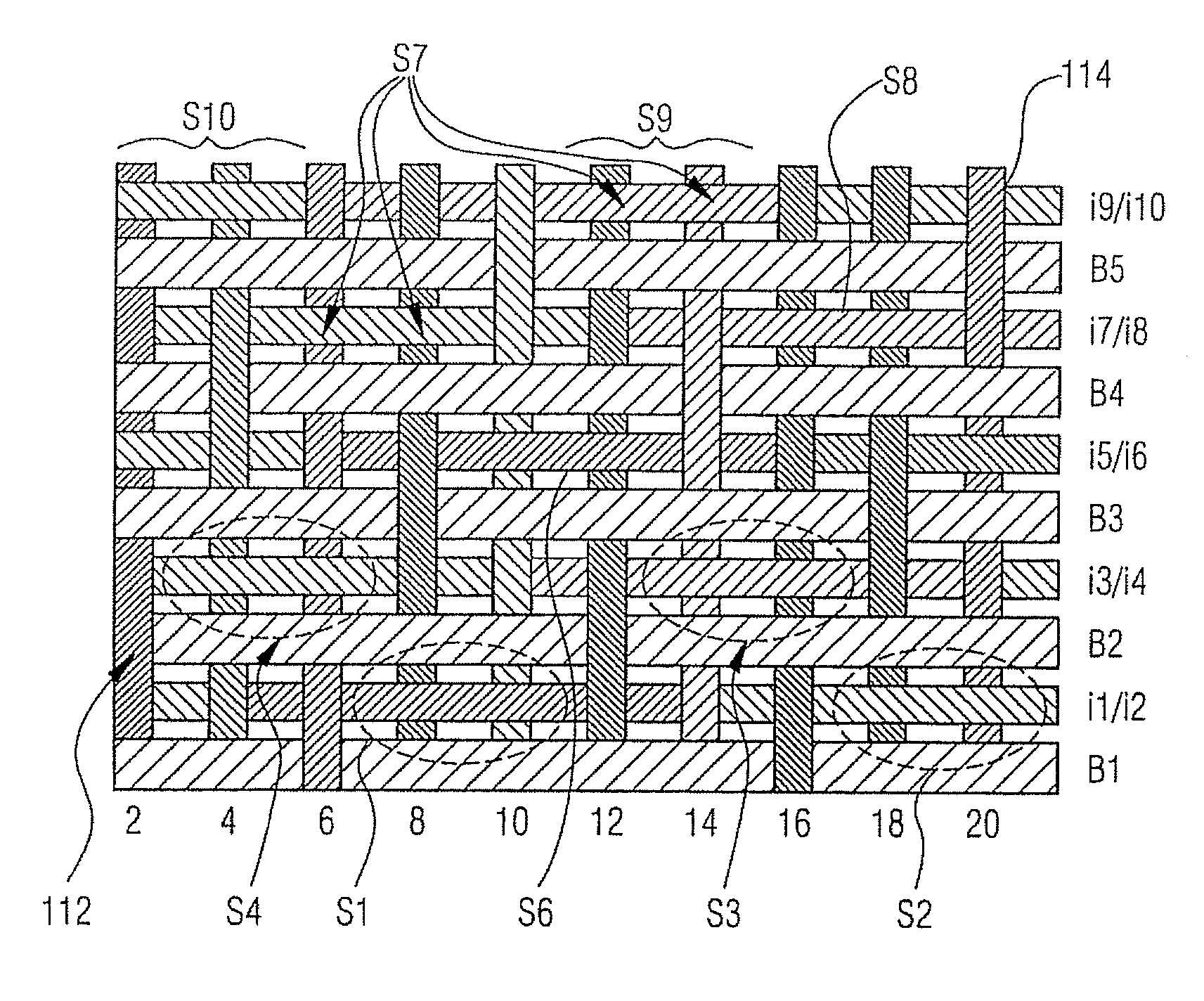
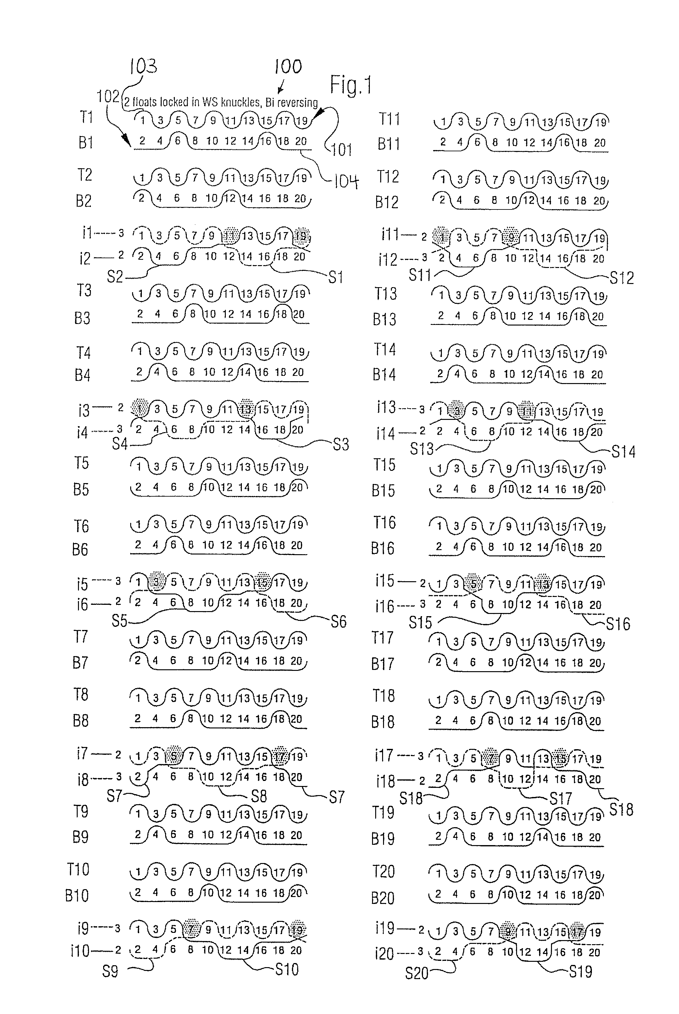
[0029]Referring now to the drawings, and more particularly to FIG. 1, there is shown, in the transverse thread direction, an inventive paper machine mesh 100 constructed as a forming mesh. In the representation in FIG. 1 there is shown a repeat unit of the weave structure of the mesh 100.
[0030]The forming mesh 100 has upper longitudinal threads 1,3,5,7,9,11,13,15,17 and 19 constructed as warp threads and lower longitudinal threads 2,4,6,8,10,12,14,16,18 and 20 constructed as warp threads. The longitudinal threads extend in this case perpendicularly from the drawing plane of FIG. 1.
[0031]Furthermore, the forming mesh 100 has binder threads it to i20 which are arranged in binder thread pairs it and i2, i3 and i4 to i19 and i20.
[0032]Also, the forming mesh 100 has upper transverse threads T1 to T20 constructed as weft threads and lower transverse threads B1 to B20 constructed as weft threads. On the forming mesh 100 presented in FIG. 1, the ratio of the number of binder thread pairs it...
second embodiment
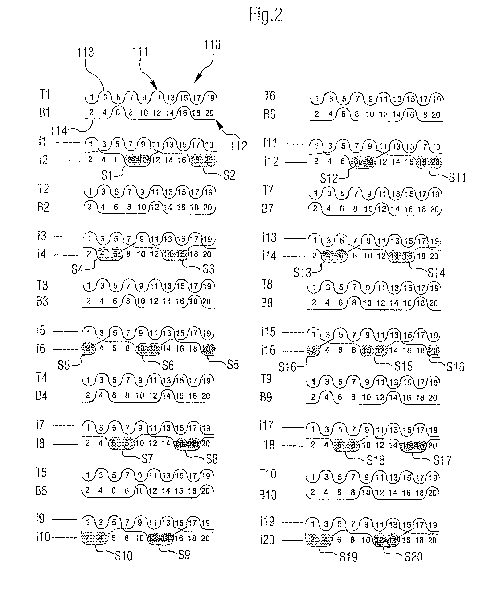
[0056]FIG. 2 shows an inventive paper machine mesh 110 constructed as a forming mesh.
[0057]The mesh 110 presented in FIG. 2 differs essentially from the forming mesh 100 presented in FIG. 1 in that the ratio of the number of binder thread pairs i1 and i2 to i19 and i20 and upper transverse threads T1 to T10 together to the number of lower transverse threads B1 to B10 is 2:1. Mesh 100 includes the outer side 113 of the upper fabric layer 111 and the outer side 114 of the lower fabric layer 112.
[0058]Furthermore, tie segments formed by binder threads of the same kind from directly adjacent binder thread pairs are—unlike in FIG. 1—directly adjacent each other in the transverse thread direction. This means that for example the binder threads of a first kind i2, i3, i6, i7, i10, i11, i14, i15, i18 and i19 form together with the corresponding lower transverse threads the tie segments S2, S3, S6, S7, S10, S11, S14, S15, S18 and S19, whereby for example the tie segments S2 and S3, which are...
PUM
Abstract
A paper machine mesh, in particular forming mesh, includes an upper and a lower fabric layer and with binder threads to join the two fabric layers, whereby the lower fabric layer is formed by the binder threads, lower transverse threads and, woven therewith and extending transverse thereto, lower longitudinal threads, whereby the lower fabric layer has a weaving pattern which is repeated in lower repeats, whereby the binder threads are arranged in pairs and the binder threads of each pair are interchangingly woven with upper and with lower longitudinal threads, whereby each binder thread pair is flanked on both sides respectively by one lower transverse thread and each of the two flanking lower transverse threads is woven in periodic sequence with lower longitudinal threads as follows: i) the flanking lower transverse thread continually crosses several directly consecutive lower longitudinal threads on the outer side of the lower fabric layer; and ii) the flanking lower transverse thread continually crosses a lower longitudinal thread between the upper and the lower fabric layer and forms a thread knuckle. Within the lower repeat:i) each binder thread of each pair with lower longitudinal threads forms at least one tie segment and each tie segment is formed in that the respective binder thread of the pair continually crosses two or more directly consecutive lower longitudinal threads on the outer side of the lower fabric layer; andii) the tie segments of each binder thread pair are arranged relative to the lower transverse threads flanking said segments such that:a) the two flanking lower transverse threads continually cross on the outer side of the lower fabric layer at least the same lower longitudinal threads which together with the binder threads of the pair form the tie segments;b) the one of the two flanking lower transverse threads forms respectively one knuckle with the lower longitudinal thread which directly precedes the corresponding tie segment; andc) the other of the two flanking lower transverse threads forms respectively one knuckle with the lower longitudinal thread which directly follows the corresponding tie segment.
Description
BACKGROUND OF THE INVENTION[0001]1. Field of the Invention[0002]This invention relates to a paper machine mesh, in particular a forming mesh.[0003]2. Description of the Related Art[0004]Forming meshes are used in the forming section of a paper machine. During the forming process, a fiber suspension from the headbox of the paper machine is applied to one forming mesh or to two forming meshes (in the case of gap formers). It is an object of the forming mesh in this case to dewater the fiber suspension and to form a fibrous web, whereby as little cellulosefiber and filler material as possible should be separated from the fiber suspension during the dewatering process.[0005]The quality of the formed fibrous web is co-defined in this case to a great extent by the structure of the surface of the forming mesh facing the fibrous web (paper side). The life of the forming mesh, on the other hand, is greatly influenced by the structure of the surface of the forming mesh facing the paper machi...
Claims
Application Information
Patent Timeline
Application Date:The date an application was filed.
Publication Date:The date a patent or application was officially published.
First Publication Date:The earliest publication date of a patent with the same application number.
Issue Date:Publication date of the patent grant document.
PCT Entry Date:The Entry date of PCT National Phase.
Estimated Expiry Date:The statutory expiry date of a patent right according to the Patent Law, and it is the longest term of protection that the patent right can achieve without the termination of the patent right due to other reasons(Term extension factor has been taken into account ).
Invalid Date:Actual expiry date is based on effective date or publication date of legal transaction data of invalid patent.
Patent Type & Authority Applications(United States)

