Fluid Flow Control Regulator

a flow control and regulator technology, applied in the field of regulators, can solve the problems of increasing the inlet pressure of water, reducing the diaphragm distortion rate, and affecting the operation of valves, and improving the regulation of fluid flow, so as to improve the configuration of at least one open-faced flow control channel, improve the effect of fluid flow regulation, and improve the effect of fluid flow

Active Publication Date: 2008-10-30
NETAFIM LTD
View PDF10 Cites 32 Cited by
  • Summary
  • Abstract
  • Description
  • Claims
  • Application Information

AI Technical Summary

Benefits of technology

[0011]An aspect of some embodiments of the invention relates to providing a fluid flow regulator having an elastic diaphragm and improved configuration of at least one open-faced flow control channel. The improved configuration provides for improved regulation of fluid flow and enables injection molds used for producing the regulator to be relatively easily modified to change a regulated flow rate that the regulator provides.
[0013]According to an aspect of some embodiments of the invention, the channel has a substantially uniform depth along its length and the sidewalls converge toward each other so that the channel narrows with channel distance and channel cross-section decreases with channel distance substantially only in proportion to the channel narrowing. A rate of increase in channel flow resistance as a function of channel cover length therefore increases with cover length and thereby with inlet pressure. The narrowing of the at least one channel, in accordance with an embodiment of the invention, compensates for the decrease in rate of increase of cover length with inlet pressure and moderates the dependence of output fluid flow provided by the regulator on inlet fluid pressure.
[0016]The inventor has found that for some ranges of output flow rates typically used in irrigation applications, a regulated flow rate provided by a regulator in accordance with an embodiment of the invention may readily be adjusted by adjusting substantially only the depth of the regulator's flow control channels. Increasing the depth increases the output flow rate of the regulator and decreasing the depth decreases the output flow rate and an increase or decrease in channel depth does not substantially affect the regulating function of the regulator. In some instances for which a change in depth does compromise flow rate regulation, flow rate regulation can generally be satisfactorily improved by a relatively easily accomplished change in sidewall convergence angle.
[0017]Assuming the regulator flow channels are formed by injection molding, because the bottom of each of the at least one channel is planar and lies in a same plane parallel to the support shelf of the diaphragm, an injection mold used to provide the channels can often relatively easily be adjusted to adjust the channel depth. For example, in the injection molding process, the flow channels are formed by protrusions in an injection mold that are negative reliefs of the at least one channel. Assume that the regulator is formed with relatively deep flow control channels and provide a regulated output flow rate that is too large. The mold used to produce the regulator channels can relatively easily be modified to reduce the flow rate by milling off a desired amount of the flow channel protrusions so that the mold produces shallower flow control channels.

Problems solved by technology

However, as distortion of the regulator diaphragm approaches the support shelf, the rate of distortion of the diaphragm with increase in water inlet pressure departs from linearity and decreases with increasing inlet pressure.
Whereas configuring flow control channels with decreasing depth and increasing width enables flow regulators to be made smaller, the relationships between channel depth, width and diaphragm characteristics are relatively complicated and modifying injection molds used to produce the regulators to modify the flow rates they provide is often a tedious and relatively expensive job.
Furthermore, because the channels get progressively narrower at distances closer to the junction, i.e. at smaller channel distances, the channels are prone to clogging with dirt and particulate debris carried by the water.

Method used


Image

  • Fluid Flow Control Regulator
  • Fluid Flow Control Regulator
  • Fluid Flow Control Regulator

Examples


Embodiment Construction

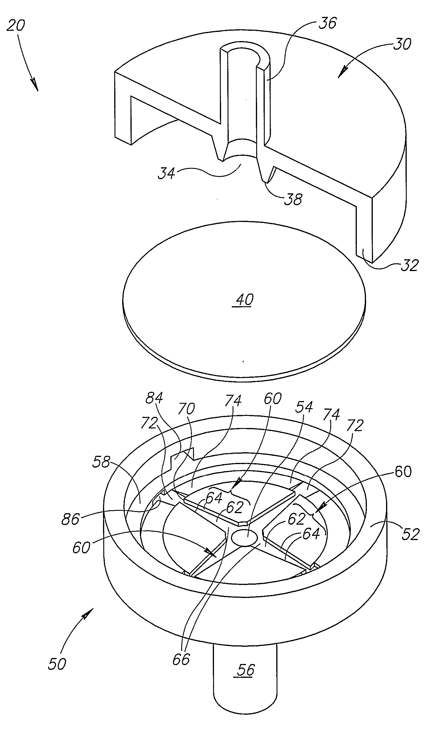
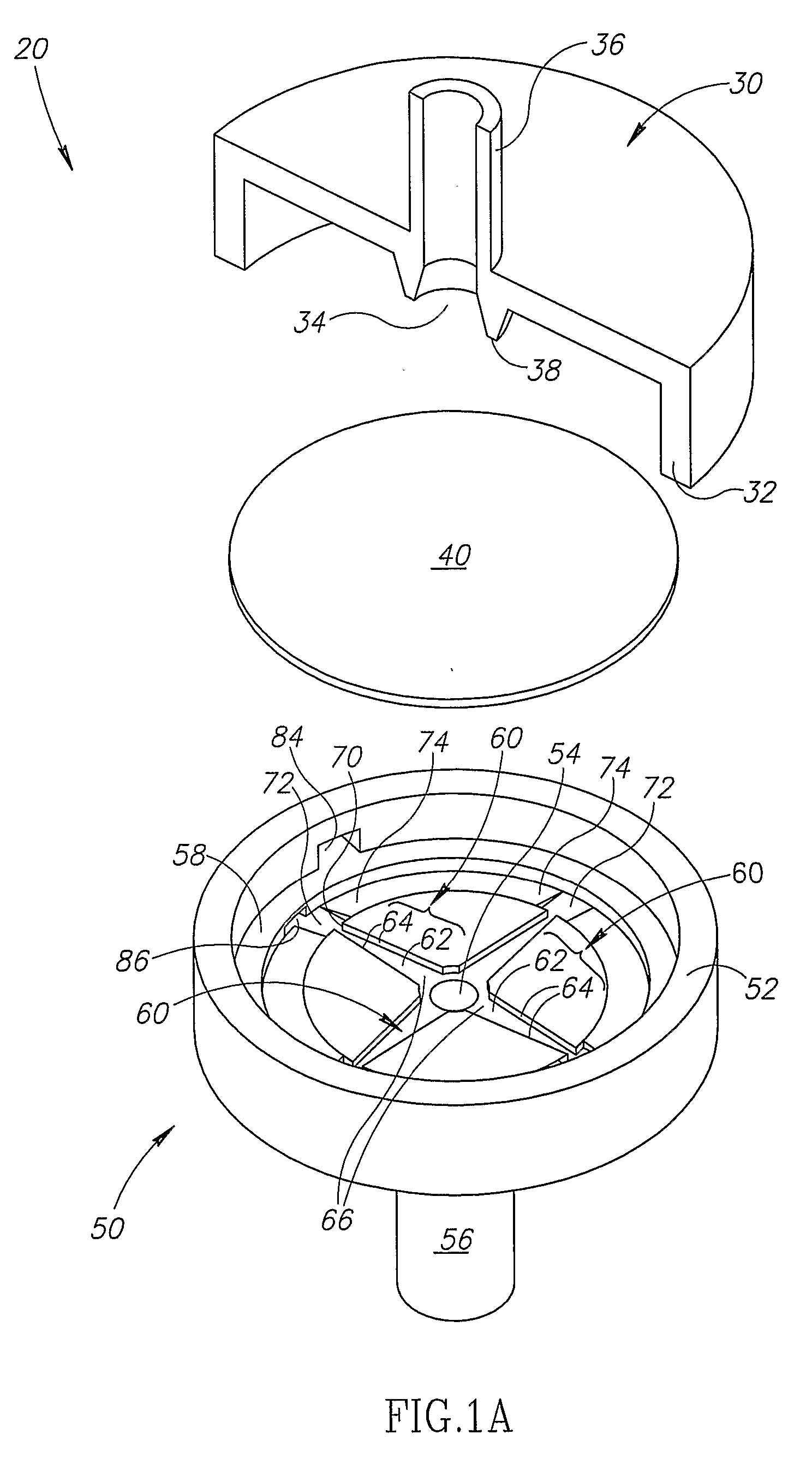
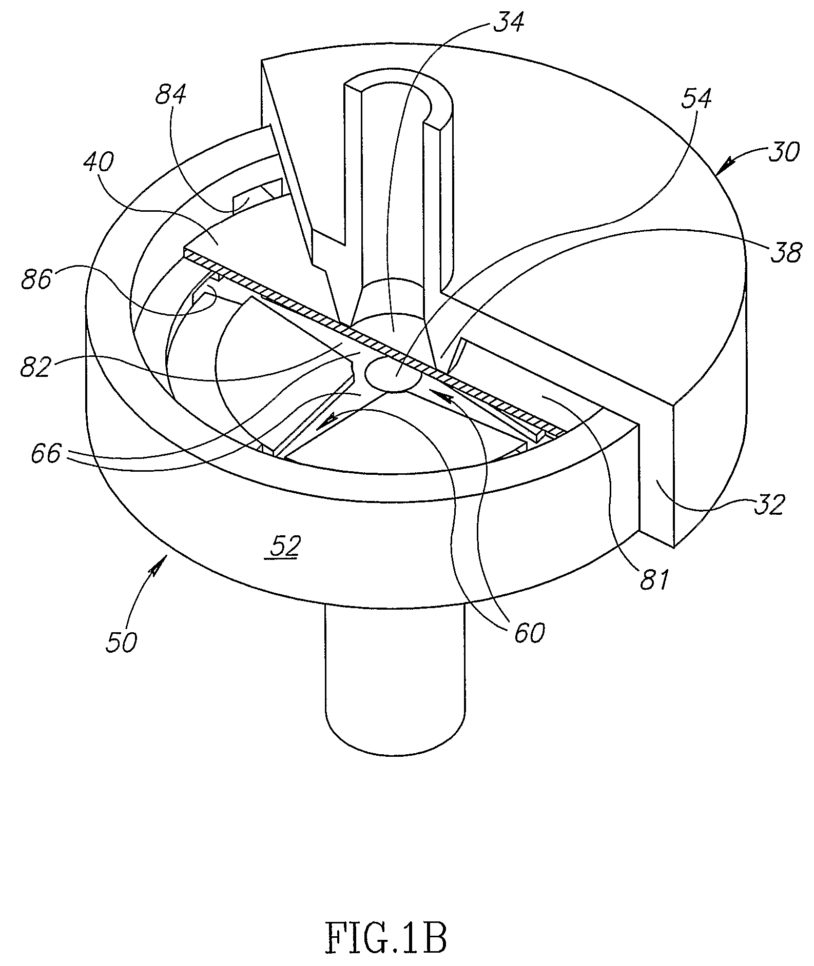
[0030]FIG. 1A schematically shows an exploded and partially cutaway view of a flow control regulator 20, in accordance with an embodiment of the invention. FIG. 1B schematically shows an assembled, partially cutaway, view of flow control regulator 20 shown in FIG. 1A. For convenience of presentation it is assumed that regulator 20 is used to control flow of water.

[0031]Regulator 20 optionally comprises an inlet cowling 30, a diaphragm 40 and an outlet cowling 50. Optionally, inlet cowling 30 is injection molded from a suitable plastic as an integral unit using any of various methods known in the art. Optionally, outlet cowling 50 is similarly formed by injection molding as a single integral unit.

[0032]Inlet cowling 30 optionally has a rim 32 and is formed with a regulator inlet port 34 and an input coupling tube 36 having any shape suitable for coupling the regulator to a source of water. An optionally annular diaphragm scaffold 38 is formed on an inside surface of inlet cowling 30 ...


PUM


Abstract

A fluid flow regulator (20) comprising: a fluid inlet port (34) and a fluid outlet port (54); at least one open-faced flow control channel (60) defined by a planar bottom (62) and two side-walls (64) that communicates with the outlet port (54) at a junction (66) and has a cross-section that decreases with distance from the junction; an elastic diaphragm (40); a support shelf (58) on which the diaphragm (40) seats and which supports the diaphragm (40) along a planar contour parallel to the bottom of each of the at least one channel (60); wherein to regulate fluid flow, with increasing inlet fluid pressure the diaphragm (40) covers portions of the open face that are farther from the junction (66) in a region where the cross-section decreases with distance from the junction (66).

Description

FIELD OF THE INVENTION[0001]The invention relates to regulators for controlling the flow of a fluid.BACKGROUND OF THE INVENTION[0002]Fluid flow regulators, particularly regulators used for controlling flow of water in irrigation systems, often control flow of water by controlling the resistance to flow of the water through at least one relatively small flow control channel. Relatively small water flow regulators used for irrigation applications typically provide regulated flow rates between about 10 and 100 liters per hour (l / h) and have components usually formed from plastics by injection molding.[0003]The regulators generally comprise an inlet and an outlet through which water respectively enters and exits the regulator and an elastic diaphragm that prevents water that enters the inlet from flowing directly to the outlet. The inlet and outlet are usually located so that they face each other, with the diaphragm seated on a support shelf and located between them. The diaphragm const...

Claims


Application Information

Patent Timeline
Patent Type & Authority Applications(United States)
IPC IPC(8): B05B1/30G05D7/01
CPCA01G25/023F16K15/141F16K17/085G05D7/0113Y10T137/7762Y10T137/7788
Inventor KEREN, RON
Owner NETAFIM LTD
Why Eureka
Try Eureka