
Liquid crystal display device

Active Publication Date: 2008-10-30
FUJIFILM CORP
View PDF5 Cites 3 Cited by
  • Summary
  • Abstract
  • Description
  • Claims
  • Application Information

AI Technical Summary

Benefits of technology

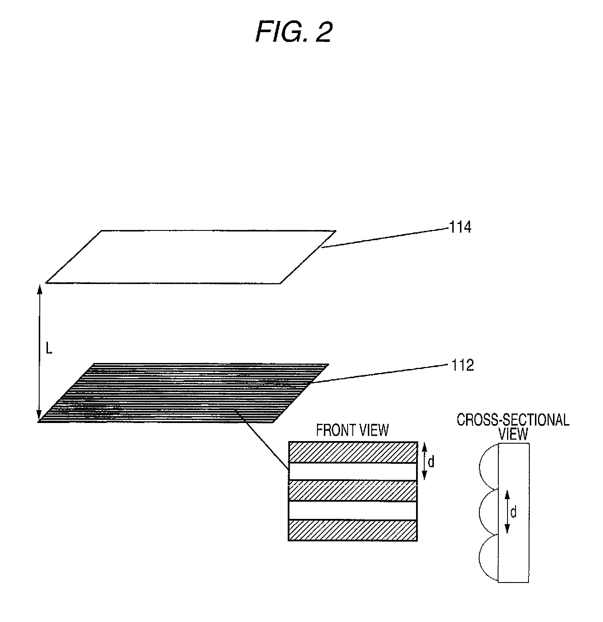
[0009]However, in liquid crystal display devices using the foregoing optical member having scattering properties (for example, optical films and optical sheets), in the case where an optical member having periodicity such as the foregoing prism sheet is disposed between a backlight and a liquid crystal layer, fringe-shaped or concentric display unevenness called “moiré” is generated through interference with a periodic pattern of pixels of a liquid crystal cell. In particular, for the purpose of increasing the convergence of the optical member having periodicity or reducing the costs, in the case where the structure has a period of 75μ or more, the generation of moiré becomes remarkable, resulting in a problem.
[0010]Also, even in the case where a low refractive index layer is provided, it is required to more reduce the glare.
[0011]An aspect of the invention is to provide a liquid crystal display device having a high contrast in any of a bright room and a dark room and capable of minimizing the deterioration of an image quality to be caused due to moiré or the like.
[0030]According to the invention, it is possible to provide a liquid crystal display device having a high contrast and capable of suppressing moiré.
[0031]Also, according to the invention, in a certain embodiment, it is possible to provide a liquid crystal display device capable of suppressing moiré and having a wide viewing angle characteristic and wide color reproducibility.

Problems solved by technology

However, in liquid crystal display devices using the foregoing optical member having scattering properties (for example, optical films and optical sheets), in the case where an optical member having periodicity such as the foregoing prism sheet is disposed between a backlight and a liquid crystal layer, fringe-shaped or concentric display unevenness called “moiré” is generated through interference with a periodic pattern of pixels of a liquid crystal cell.
In particular, for the purpose of increasing the convergence of the optical member having periodicity or reducing the costs, in the case where the structure has a period of 75μ or more, the generation of moiré becomes remarkable, resulting in a problem.

Method used


Image

  • Liquid crystal display device
  • Liquid crystal display device
  • Liquid crystal display device

Examples


example 1

(1) Coating of Light Scattering Layer:

[0210]A triacetyl cellulose film (TAC-TD80U, refractive index: 1.49, manufactured by Fujifilm Corporation) having a thickness of 80 μm as a transparent support was unwound in a rolled shape; and a coating solution A for light scattering layer was coated by a die coating method using the following apparatus configuration under the following coating condition was coated. After drying at 30° C. for 15 seconds and further 90° C. for 20 seconds, the coating layer was cured upon irradiation with ultraviolet rays at a dose of 90 mJ / cm2 using an air-cooling metal halide lamp (manufactured by Eyegraphics Co., Ltd.) of 160 W / cm while purging with nitrogen (oxygen concentration: 0.05% by volume), thereby forming a 12 μm-thick light scattering layer having antiglare properties, following by winding up.

Basic Condition

[0211]As a slot die 13 as shown in FIG. 5, one having an upstream side lip land length IUP of 0.5 mm, a downstream side lip land length ILO of ...

reference example 1

[0243]A liquid crystal display device was prepared in the same manner as in Example 1, except for using a sample 1-2 as the light scattering film in place of the sample 1-1. At that time, the level of the contrast was rated as “A”; the level of the moiré was rated as “C”; and the level of the black tightness was rated as “A”.

[0244]The sample 1-2 was prepared in the same manner as in Example 1, except that the coating solution for light scattering layer was changed from the coating solution A to the coating solution B and that the coating condition was changed to the foregoing condition.

reference example 2

[0245]A liquid crystal display device was prepared in the same manner as in Example 1, except for using a sample 1-3 as the light scattering film in place of the sample 1-1. At that time, the level of the contrast was rated as “C”; the level of the moiré was rated as “A”; and the level of the black tightness was rated as “B”.

[0246]The sample 1-3 was prepared in the same manner as in Example 1, except that the coating solution for light scattering layer was changed from the coating solution A to the coating solution C and that the coating condition was changed to the foregoing condition.


PUM


Abstract

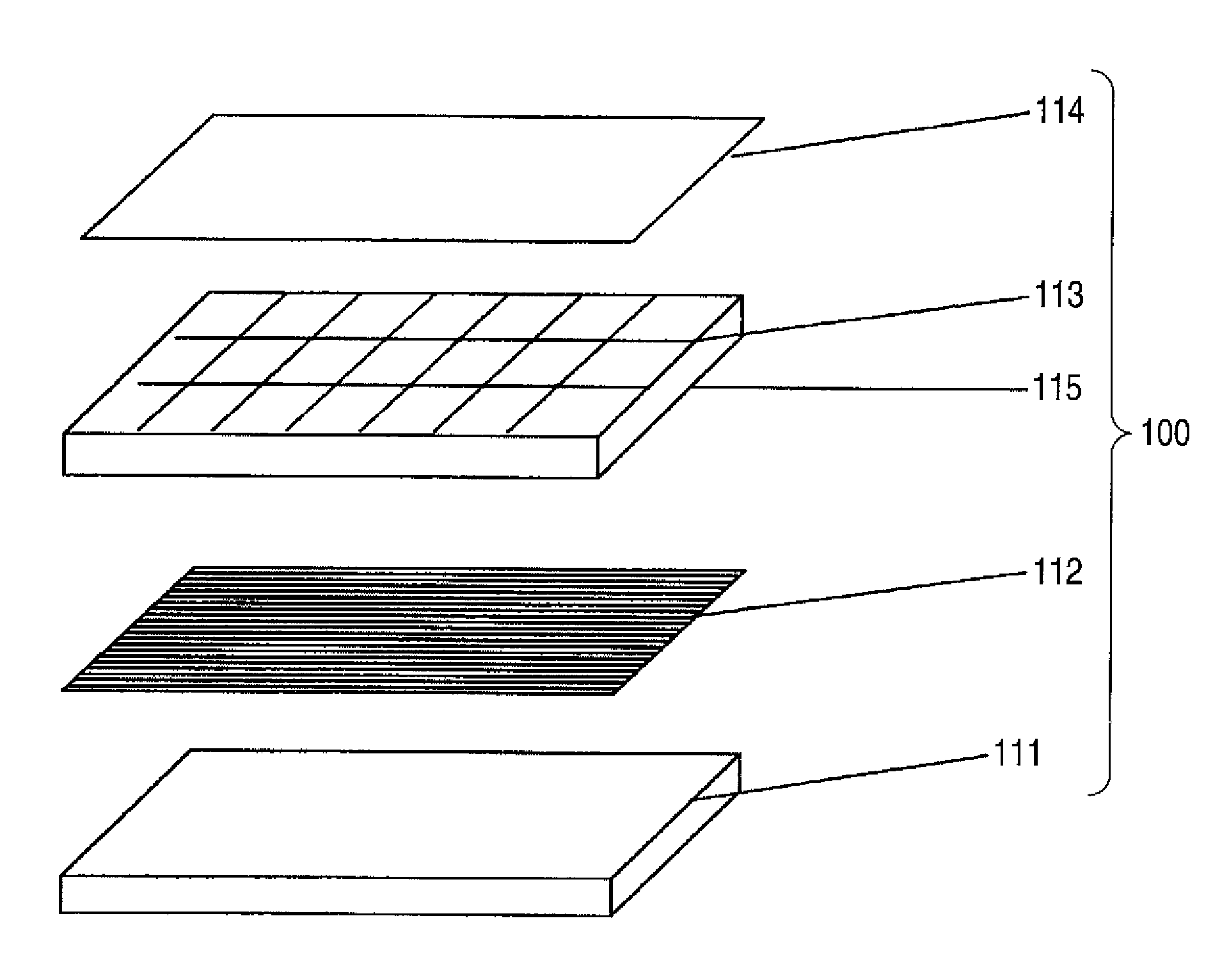
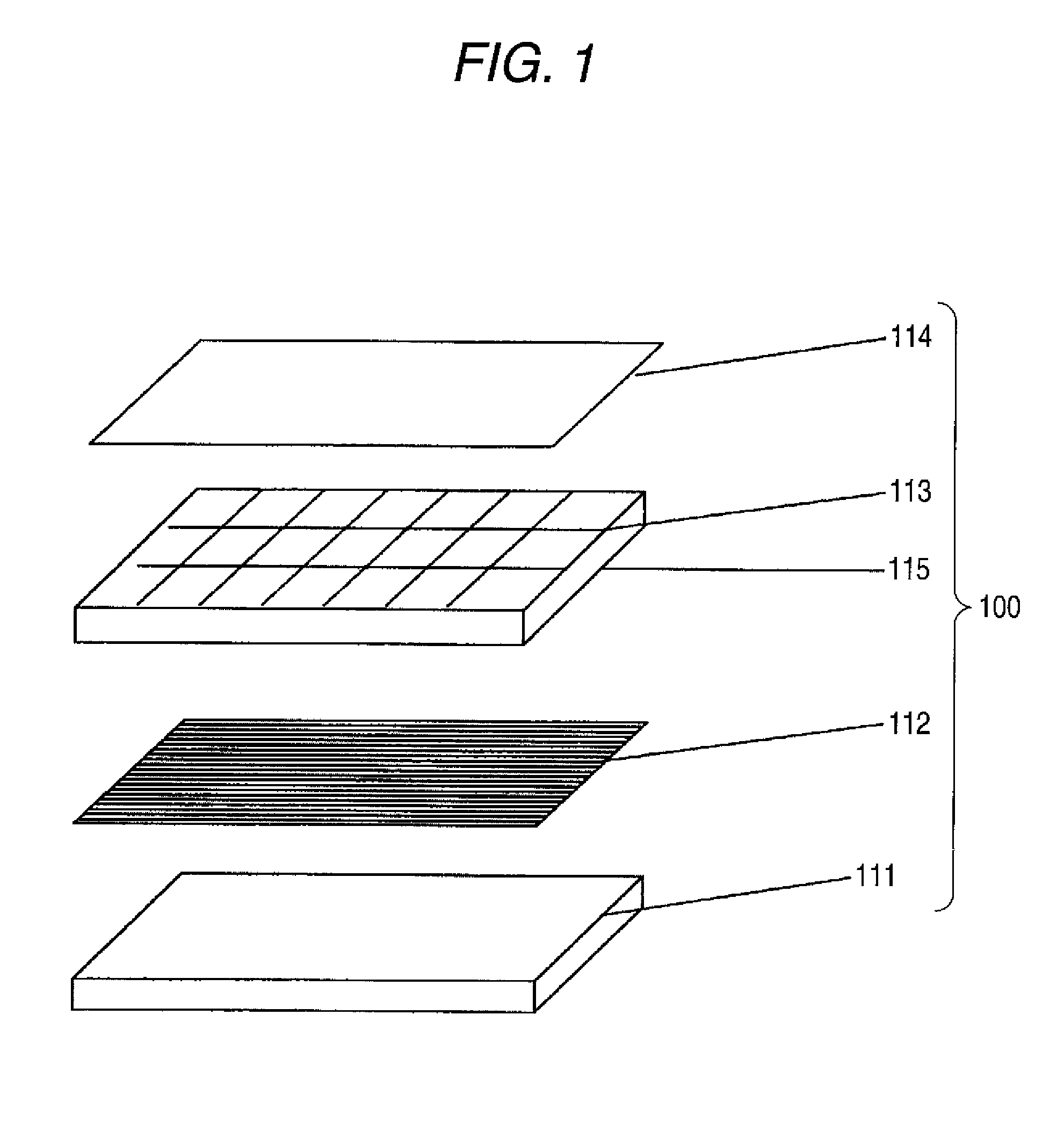
A liquid crystal display device includes a light source, at least one optical member having a periodic structure of 75 μm or more, pixels disposed in a matrix state, and at least one optical member with light scattering properties.

Description

CROSS-REFERENCE TO RELATED APPLICATIONS[0001]This application claims the benefit of Japanese Patent Application JP 2007-115603, filed Apr. 25, 2007, the entire content of which is hereby incorporated by reference, the same as if set forth at length.FIELD OF THE INVENTION[0002]The present invention relates to a liquid crystal display device.BACKGROUND OF THE INVENTION[0003]As a display device which is used for OA appliances such as monitors for word processors, notebook personal computers and personal computers, mobile terminals, television sets and the like, a cathode ray tube (CRT) has been mainly used until now. In recent years, a liquid crystal display device is being widely used in place of CRT because it is slim, lightweight and low in consumed electric power. The liquid crystal display device includes a liquid crystal cell and a polarizing plate. The polarizing plate is in general composed of a protective film and a polarizing film and obtained by dyeing a polarizing film comp...

Claims


Application Information

Patent Timeline
IPC IPC(8): G02F1/1335G02B5/02
CPCG02B3/0006G02F1/133502G02F1/133504G02F1/133526G02F2001/133562G02F2001/133567G02F1/133562G02F1/133567
Inventor WATANABE, JUNSANETO, RYUJIMATSUNAGA, NAOHIRO
Owner FUJIFILM CORP
Learn More