
Aircraft interior sidewall paneling systems provide enhanced cabin lighting and ventilation

a technology for interior sidewall panels and passenger aircraft, which is applied in the field of interior sidewall paneling systems for passenger aircraft, can solve the problems of disconcertingly visible light sources, difficult for some passengers, and easy movement around, and achieve enhanced seating areas, enhanced space and accent interior features, and unique “look and feel

Active Publication Date: 2008-10-30
THE BOEING CO
View PDF5 Cites 25 Cited by
  • Summary
  • Abstract
  • Description
  • Claims
  • Application Information

AI Technical Summary

Benefits of technology

[0006]In accordance with the exemplary embodiments described herein, aircraft interior paneling systems are provided that create a unique “look and feel” to an aircraft's cabin interior and that enhance space and accent interior features by the novel use of lighting. The systems afford a futuristic cabin sidewall that engender a unique passenger experience by providing a window shape optimized to provide a view out of the airplane for different sized passengers, an intimate yet spacious sidewall environment, lighting that does not shine directly into the passengers' eyes, and floor safety lighting that enables passengers to more easily find their luggage stowed beneath the seats and move around inside of the aircraft safely. The paneling systems take into consideration passenger space and lighting requirements of modern passenger aircraft, i.e., enhanced seating area and innovative window treatments.
[0009]The exemplary panel assembly further includes a kick panel at its lower end, which in one embodiment, can be formed integral to the wall panel, and in an alternative embodiment, can be provided independently of the panel, and in modular lengths that are the same as or different than the width of the panel. Additionally, the kick panel can incorporate, or provide the ducting and / or grillwork for cabin ventilation or decompression. Advantageously, the kick panel may also provide the location and mounting for one or more indirect lighting sources that are arranged to radiate light onto the cabin floor at the feet of the seated passengers, such that they can see where to place their feet and easily find carryon luggage and other items stowed on the floor of the cabin beneath the seats.

Problems solved by technology

Since the overhead light washes down the panels in the conventional design, when the passengers look up, the light source is disconcertingly visible to them.
Conversely, the wall and floor areas adjacent to the passenger's feet are relatively dark, making it difficult, for example, for them to move around easily in such areas and to find carryon luggage stowed on the floor of the cabin beneath the seats.
Additionally, since the passengers' windows are oval shaped and relatively small in area, they make it difficult for some passengers, e.g., those not situated immediately adjacent to a window, to see out of the aircraft easily without having to stretch or stoop.
A long-felt but as yet unsatisfied need therefore exists for interior sidewall paneling systems for passenger aircraft that overcome the above lighting problems and provide passengers of all sizes and seat positions with an enhanced view out of the aircraft.

Method used


Image

  • Aircraft interior sidewall paneling systems provide enhanced cabin lighting and ventilation
  • Aircraft interior sidewall paneling systems provide enhanced cabin lighting and ventilation
  • Aircraft interior sidewall paneling systems provide enhanced cabin lighting and ventilation

Examples


Embodiment Construction

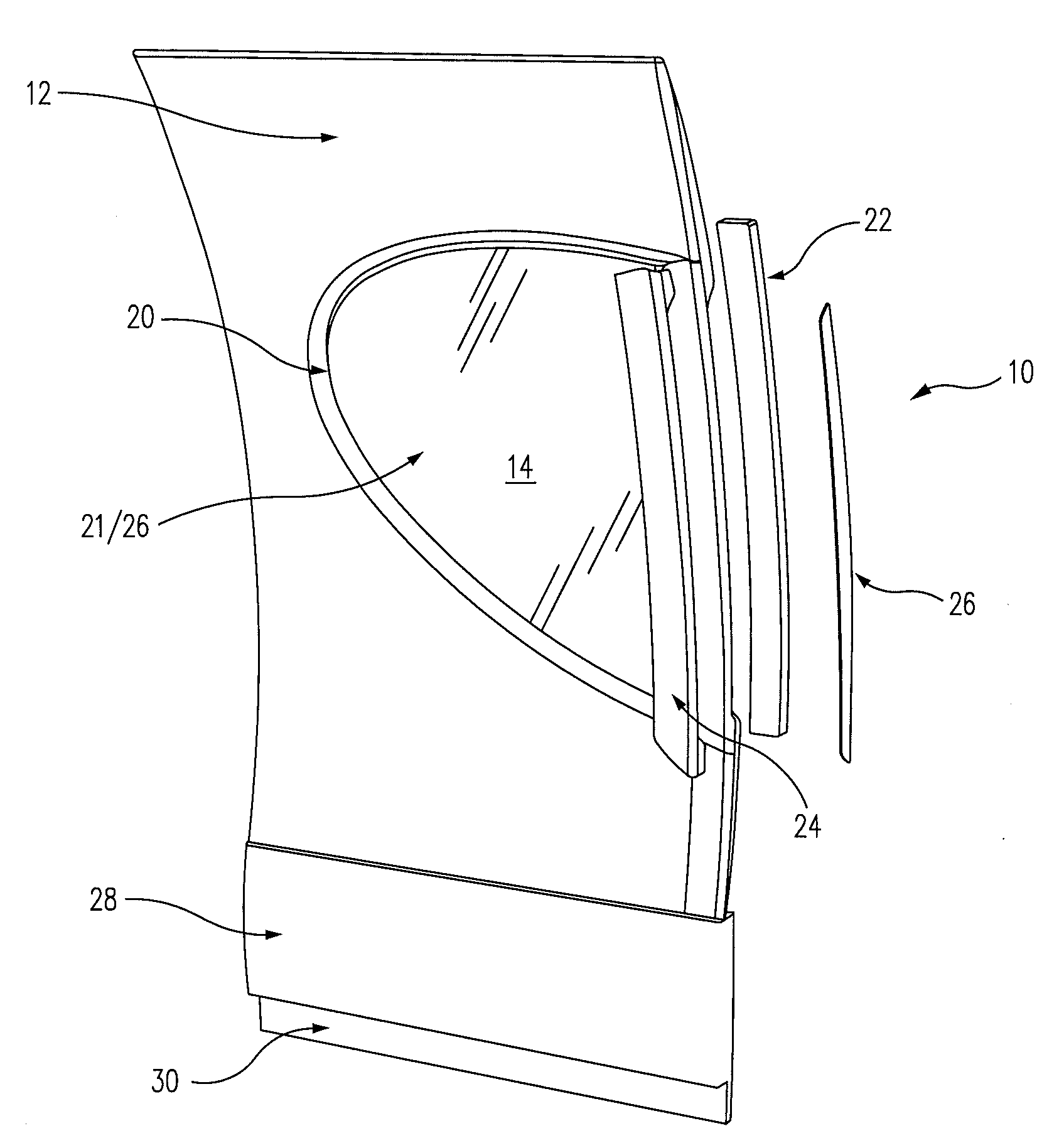
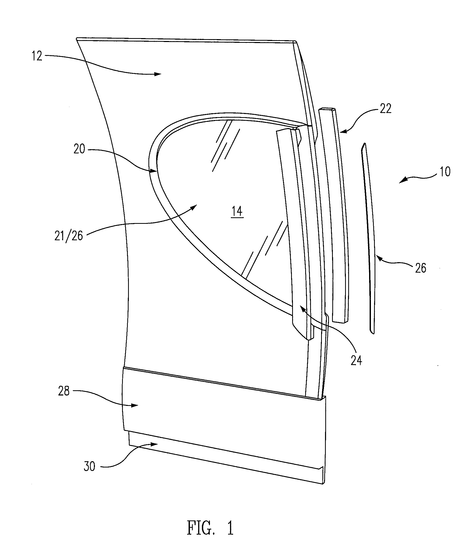
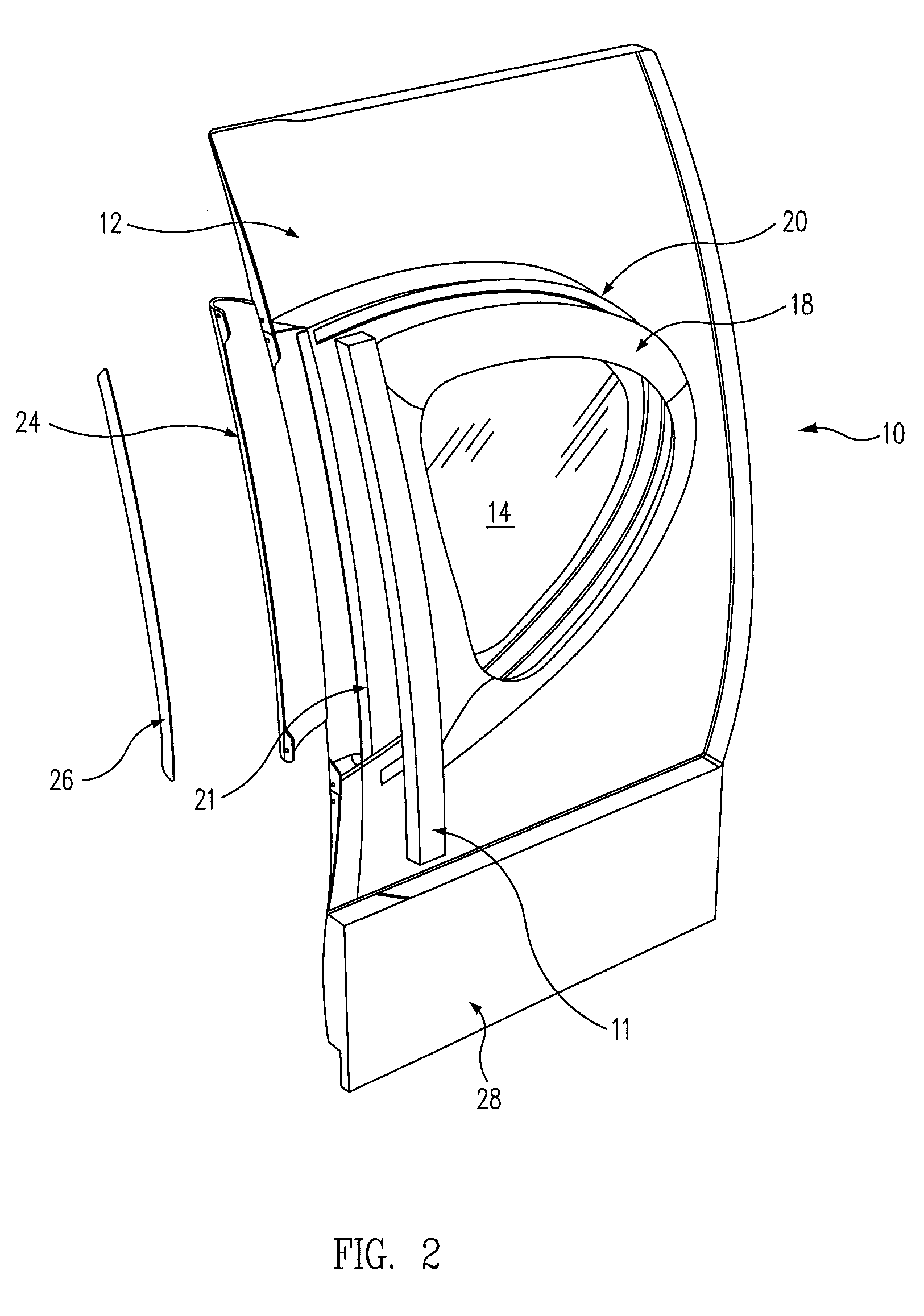
[0023]FIG. 1 is a right side, interior, exploded perspective view of an exemplary embodiment of an aircraft sidewall panel assembly 10 in accordance with the paneling system of the present disclosure, and FIG. 2 is an exterior, left side, exploded perspective view thereof.

[0024]As illustrated in FIGS. 1 and 2, the exemplary panel assembly 10 comprises an outwardly curved, generally planar structural sidewall panel 12 formed of, e.g., a molded plastic, such as polycarbonate or polyurethane, or alternatively, a fiber reinforced matrix, such as glass or carbon fibers embedded in an epoxy resin matrix, that includes an elongated, D-shaped window opening 14 having an apex, or point of greatest curvature, which is directed rearward and tilted slightly upward relative to the horizontal, as illustrated in, e.g., the inboard elevation views of FIGS. 4, 5 and 8. The sidewall panel is curved outwardly to conform generally to the curvature of the aircraft fuselage (not illustrated), and as illu...


PUM


Abstract

An interior sidewall panel assembly for a passenger aircraft includes a generally planar sidewall structural panel having a D-shaped window opening with an apex that is directed rearward and tilted slightly upward relative to the horizontal, a window assembly disposed in the window opening, an indirect lighting module disposed at a forward edge of the D-shaped window assembly and arranged to direct light forwardly such that the light washes onto a rear margin of a structural panel of a next adjacent panel assembly located immediately forward of the light module, and a kick panel disposed at a lower margin of the structural panel that incorporates cabin ventilation or decompression ducts and vents and an accent light adapted to direct light onto a cabin floor of the aircraft.

Description

RELATED APPLICATIONS[0001]This application claims the benefit of U.S. Provisional Application 60 / 914,565, filed Apr. 27, 2007.BACKGROUND[0002]This disclosure relates to aircraft interiors in general, and in particular, to interior sidewall paneling systems for passenger aircraft that incorporate a large, unique window shape to enhance passenger visibility, forward-facing indirect sidewall lighting wash lights, substantially enhanced foot area lighting, cabin decompression ventilation, and a flexible, laterally overlapping (i.e., shingled) panel interconnection design.[0003]Currently, all passenger aircraft interior sidewall panel designs use direct lighting that radiates from above the sidewall and washes down along the panel, and also typically incorporate traditional, oval shaped windows. Since the overhead light washes down the panels in the conventional design, when the passengers look up, the light source is disconcertingly visible to them. Conversely, the wall and floor areas ...

Claims


Application Information

Patent Timeline
Patent Type & Authority Applications(United States)
IPC IPC(8): B64D47/02
CPCB64C1/066B64C1/1484B64D47/02B64D2011/0038
Inventor WENTLAND, MARK E.LEBLANC, THOMAS L.LAU, CHARLES K.
Owner THE BOEING CO
Learn More