Optical scanning device and image forming apparatus

a scanning device and image forming technology, applied in the direction of electrographic process equipment, printing, instruments, etc., can solve the problems of reducing the durability of the apparatus, deteriorating the operating life of the element, and reducing the operation life of the element, so as to increase the operating life of the light source and reduce the deterioration of optical characteristics

Active Publication Date: 2008-10-30
RICOH KK
View PDF47 Cites 59 Cited by
  • Summary
  • Abstract
  • Description
  • Claims
  • Application Information

AI Technical Summary

Benefits of technology

[0011]It is, therefore, an object of the present invention to provide an optical scanning device which can increase an operating life of a light source having two-dimensionally arranged light-emitting portions, and can also reduce the deterioration in the optical characteristics by the heat from the light source.
[0012]Another object of the present invention is to provide an image forming apparatus which can reduce the running costs and can form a high quality image.

Problems solved by technology

However, if the rotation speed of the polygon mirror is increased, the noise and vibration from a driving system are increased and the power consumption is also increased, causing a decrease in the durability of the apparatus.
Moreover, since the increase in the image output speed has a trade-off relationship relative to the increase in the image density, if the rotation speed of the polygon mirror is increased, the image quality is deteriorated along with the increase in the rotation speed.
However, it is difficult for this type of the surface-emitting laser to increase the output, and if the arrangement interval between the light-emitting parts is too short, the operating life of the element is significantly deteriorated by the heat interference between the light-emitting parts.
However, in this invention, the arrangement of the light-emitting parts is complex, and can not be easily achieved.

Method used


Image

  • Optical scanning device and image forming apparatus
  • Optical scanning device and image forming apparatus
  • Optical scanning device and image forming apparatus

Examples


embodiment 2

[0153]Next, a modification example of the optical scanning device 100 will be described. In addition, the description will be omitted for the parts similar to the parts in the above embodiment 1 and the parts the same as the parts in the above embodiment 1.

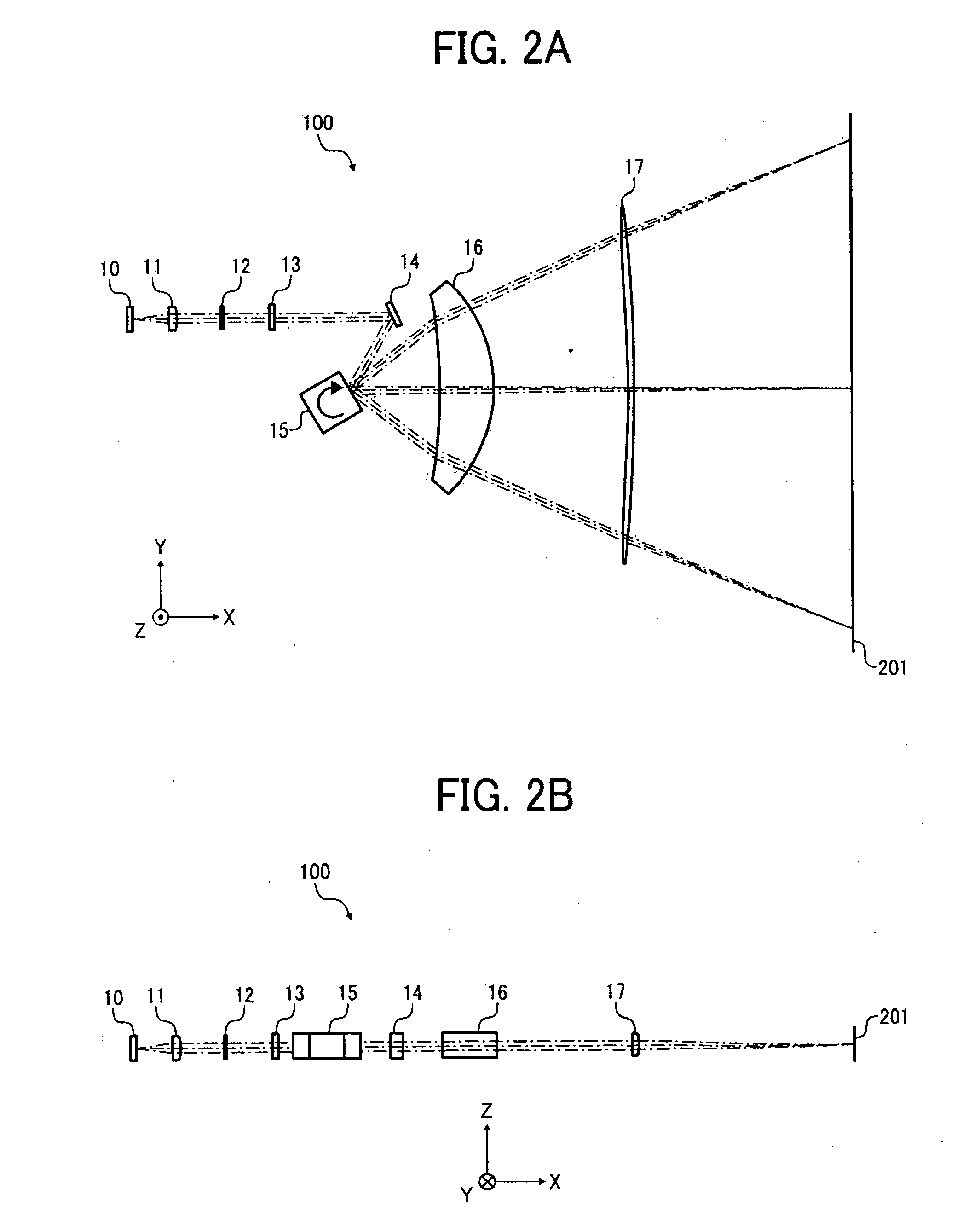
[0154]FIGS. 17A, 17B are a plan view and a side view, respectively, each illustrating a schematic structure of an optical scanning device 100′ according to the present embodiment. As illustrated in FIGS. 17A, 17B, the optical scanning device 100′ includes a light source 10, a coupling lens 14, an aperture member 12, a linear image forming lens 13, a reflection mirror 14, which are sequentially disposed on the +X side of the light source 10 in FIG. 17A, a polygon mirror 15, which is disposed on the −Y side of the reflection mirror 14 in FIG. 17A, a first scanning lens 16, and a second scanning lens 17, which are sequentially disposed on the +X side of the polygon mirror 15 in FIG. 17A.

[0155]The coupling lens 11 is a lens having the...

embodiment 3

[0181]Hereinafter, embodiment 3 of the present invention will be described with reference to FIGS. 24-29.

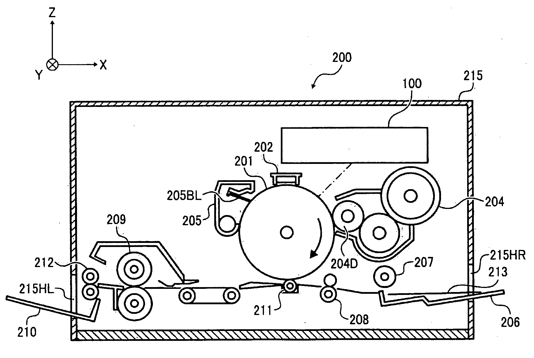
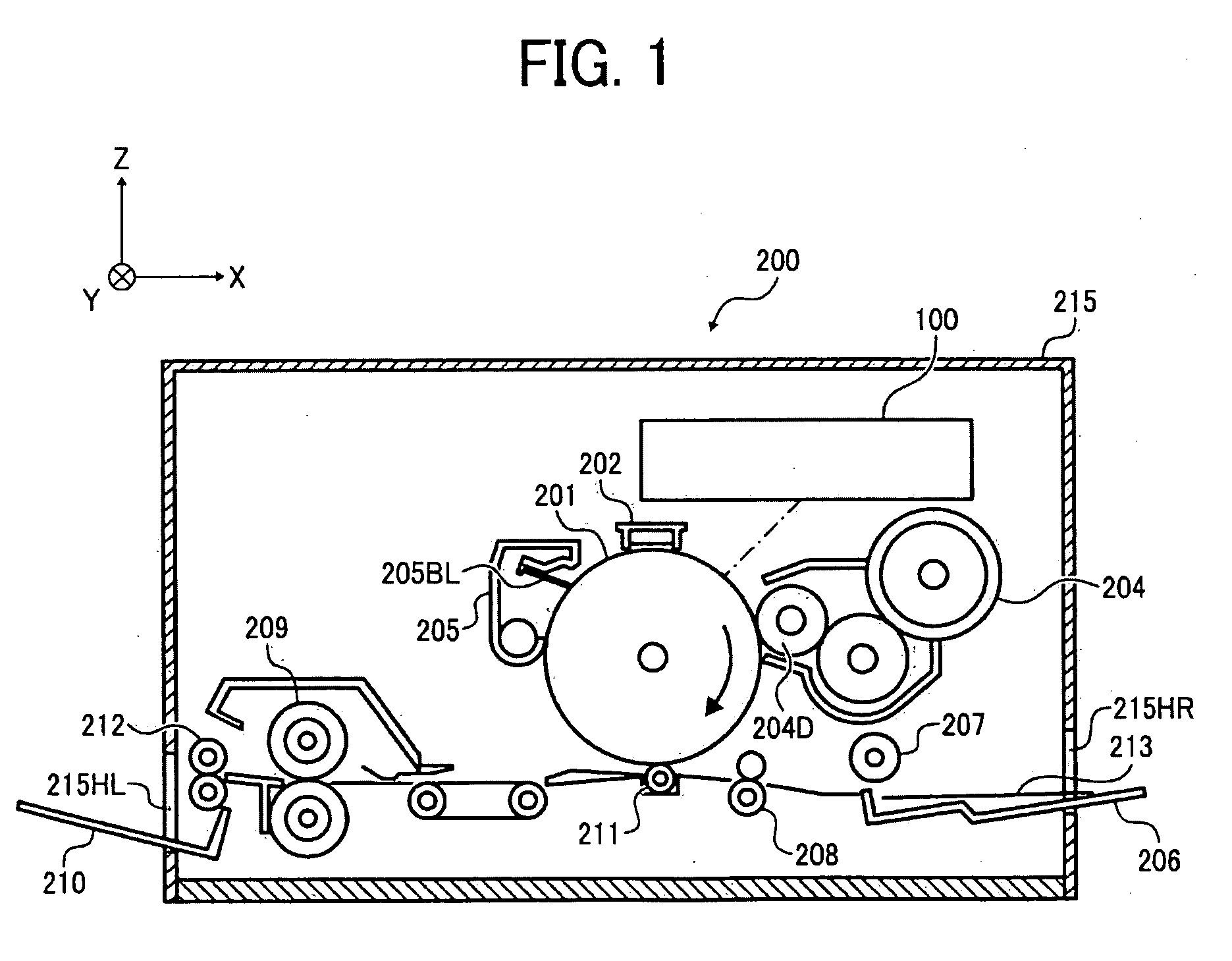
[0182]FIG. 24 illustrates a schematic structure of a printer 300 as an image forming apparatus of the embodiment 3 of the present invention.

[0183]The printer 300 is a color printer which prints an image by transferring a toner image onto a paper by means of the Carlson process. This printer 300 includes an optical scanning device 110, a photoconductive drum 201, a charger 202, a toner cartridge 204, a cleaning case 205, a paper feeding tray 206, a paper feeding roller 207, a resist roller pair 208, a transfer charger 211, a fixing roller 209, a paper discharging roller 212, a paper discharging tray 210, and a housing 220 which houses these.

[0184]The housing 220 is an approximate rectangular solid, and has openings 220HR, 220HL, which communicate with the internal space, formed on the side walls on the +X side and −X side, respectively, in FIG. 24,

[0185]The optical scanning device...


PUM


Abstract

An optical scanning device which scans a scanned surface by a plurality of light beams in a main-scanning direction includes a light source having a plurality of light-emitting portions which emit the light beams, the light-emitting portions being two-dimensionally arranged in a plane parallel to the main-scanning direction and a sub-scanning direction orthogonal to the main-scanning direction via arrangement intervals in the main-scanning direction and the sub-scanning direction, a deflector which scans the light beams in the main-scanning direction; and a scanning optical system which images the scanned light beams onto the scanned surface.

Description

PRIORITY CLAIM[0001]The present application is based on and claims priorities from Japanese Patent Application No. 2007-116318, filed on Apr. 26, 2007, and No. 2007-124141, filed on May 9, 2007, the disclosures of which are hereby incorporated by reference in their entirety.BACKGROUND OF THE INVENTION[0002]1. Field of the Invention[0003]The present invention relates to an optical scanning device using a plurality of light beams, and an image forming apparatus having the optical scanning device.[0004]2. Description of the Related Art[0005]Conventionally, as an image forming apparatus which forms an image by means of the Carlson process, there is known, for example, an image forming apparatus which forms an electrostatic latent image on a surface of a photoconductive drum by scanning the surface of a rotating photoconductive drum with optical beams, visualizes the electrostatic latent image as a toner image using toners, and forms an image by fixing the toner image onto a recording me...

Claims


Application Information

Patent Timeline
Patent Type & Authority Applications(United States)
IPC IPC(8): G03G15/04G02B26/08
CPCB41J2/473G02B26/123G03G15/043G03G15/326G03G2215/0407G03G15/0435H04N1/12H04N1/1912H04N1/1917H04N2201/0082H04N1/1135
Inventor ICHII, DAISUKEHAYASHI, YOSHINORISUZUKI, SEIZOISHIDA, MASAAKIHIRAKAWA, MAKOTO
Owner RICOH KK
Why Eureka
Try Eureka