Method of deformity correction in a spine using injectable materials

Active Publication Date: 2008-10-30
WARSAW ORTHOPEDIC INC
View PDF26 Cites 7 Cited by
  • Summary
  • Abstract
  • Description
  • Claims
  • Application Information

AI Technical Summary

Benefits of technology

[0020]In accordance with the purposes of the present invention, as embodied and broadly described herein, a method of this invention is provided for increasing the stiffness of an intervertebral disc between adjacent vertebral bodies of a spine. The intervertebral disc has an outer region being an annulus fibrosus and a central region being a nucleus pulposus. The method includes providing a syringe with a needle having a distal end approximately in the range of 16 to 25 gauge.
[0022]The method further includes testing the annulus fibrosus of the disc to ensure that the annulus fibrosus has sufficient continuity so as to retain the first flowable stage material when subsequently injected into the disc; inserting the distal end of the needle into the annulus fibrosus; injecting the first stage material through the needle and into the disc; and permitting the first stage material to become the second stage material so as to form a load bearing implant in the disc to increase the stiffness of at least a portion of the disc.
[0027]The permitting of the first stage material to become the second stage material includes curing the material. The permitting of the first stage material to become the second stage material so as to form a load bearing implant in the disc may improve the alignment of the vertebral bodies of the spine adjacent the disc. The permitting of the first stage material to become the second stage material so as to form a load bearing implant in the disc may in one preferred embodiment also accomplish one or more of the following: increase the lordosis of the vertebral bodies of the spine adjacent the disc, stiffen motion between the vertebral bodies of the spine adjacent the disc, and indirectly decompress nerve compression in the neuroforamina of the spine proximate the disc.
[0029]The method in one embodiment includes not removing any of the disc before injecting the first stage material through the needle and into the disc. In particular, the method may include not removing any of the annulus fibrosus before injecting the first stage material through the needle and into the disc, or additionally or alternatively not removing any of the nucleus pulposus before injecting the first stage material through the needle and into the disc. The method in yet another embodiment includes positioning the patient to reduce loading in the area near the vertebra immediately surrounding the disc and to reduce pressure on the disc.
[0030]It is an object of the present invention to provide a method for increasing the stiffness of an intervertebral disc between adjacent vertebral bodies of a spine.

Problems solved by technology

Intervertebral discs may be displaced or damaged due to trauma or disease.
The extruded nucleus pulposus may press on a spinal nerve, which may result in nerve damage, pain, numbness, muscle weakness, and paralysis.
Intervertebral discs may also deteriorate due to the normal aging process.
As a disc dehydrates and hardens, the disc space height will be reduced, leading to instability of the spine, decreased mobility and pain.
The removal of the damaged or unhealthy disc may allow the disc space to collapse, which would lead to instability of the spine, abnormal joint mechanics, nerve damage, as well as severe pain.
Spinal fusion, however, is disadvantageous because it restricts the patient's mobility by reducing the spine's flexibility, and it is a relatively invasive procedure.
Preformed disc implants may tear or otherwise be damaged during implantation.
In-situ cured polymers inserted into the disc under pressure can leak the material into sensitive adjacent areas.

Method used


Image

  • Method of deformity correction in a spine using injectable materials
  • Method of deformity correction in a spine using injectable materials
  • Method of deformity correction in a spine using injectable materials

Examples


Embodiment Construction

[0042]The following description is intended to convey a thorough understanding of the present invention by providing a number of specific embodiments and details involving use of a material for increasing the stiffness of an intervertebral disc. It is understood, however, that the present invention is not limited to these specific embodiments and details, which are exemplary only. It is further understood that one possessing ordinary-skill in the art, in light of known systems and methods, would appreciate the use of the invention for its intended purposes and benefits in any number of alternative embodiments, depending upon the specific design and other needs.

Description of Relevant Anatomy

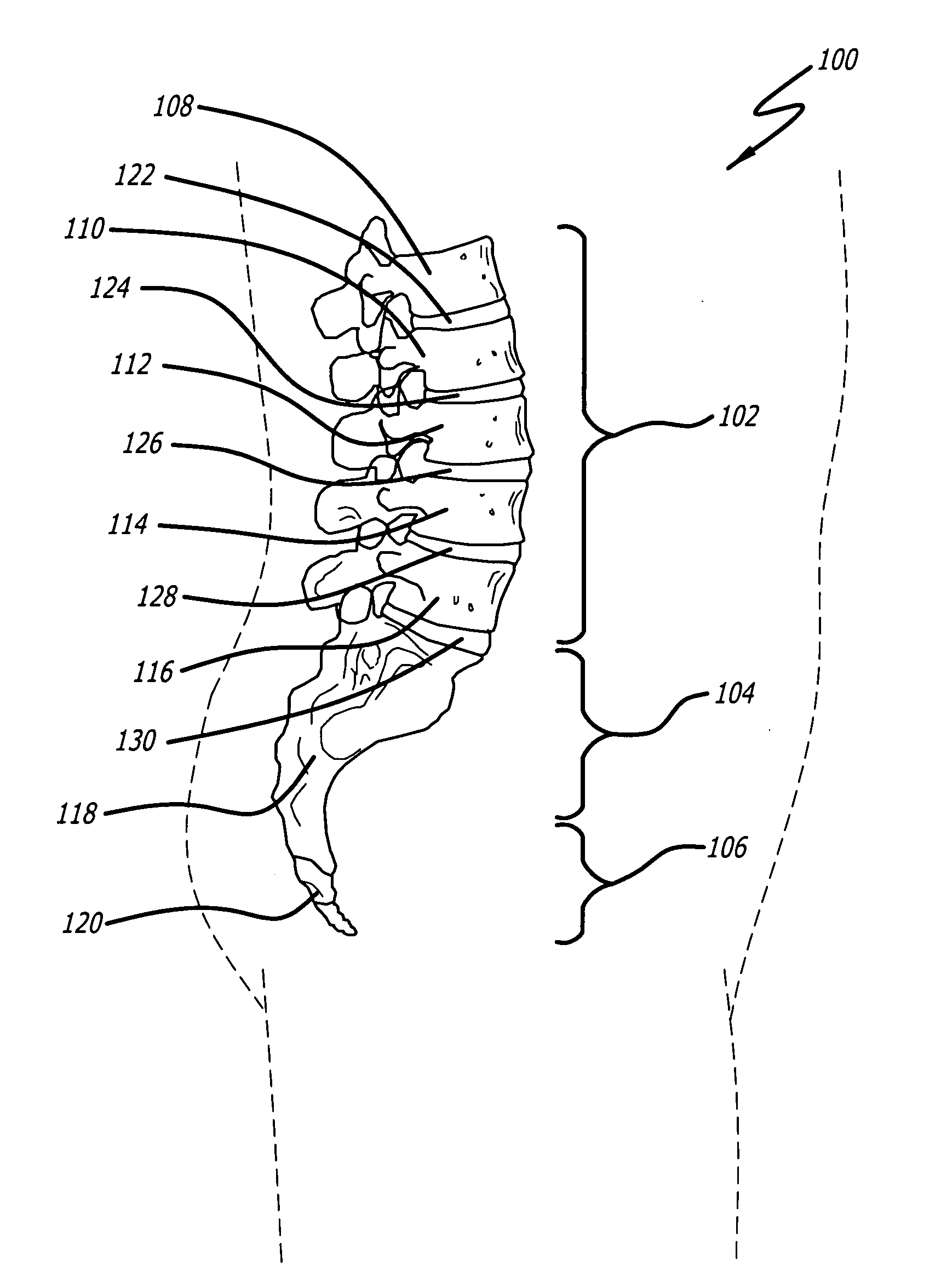
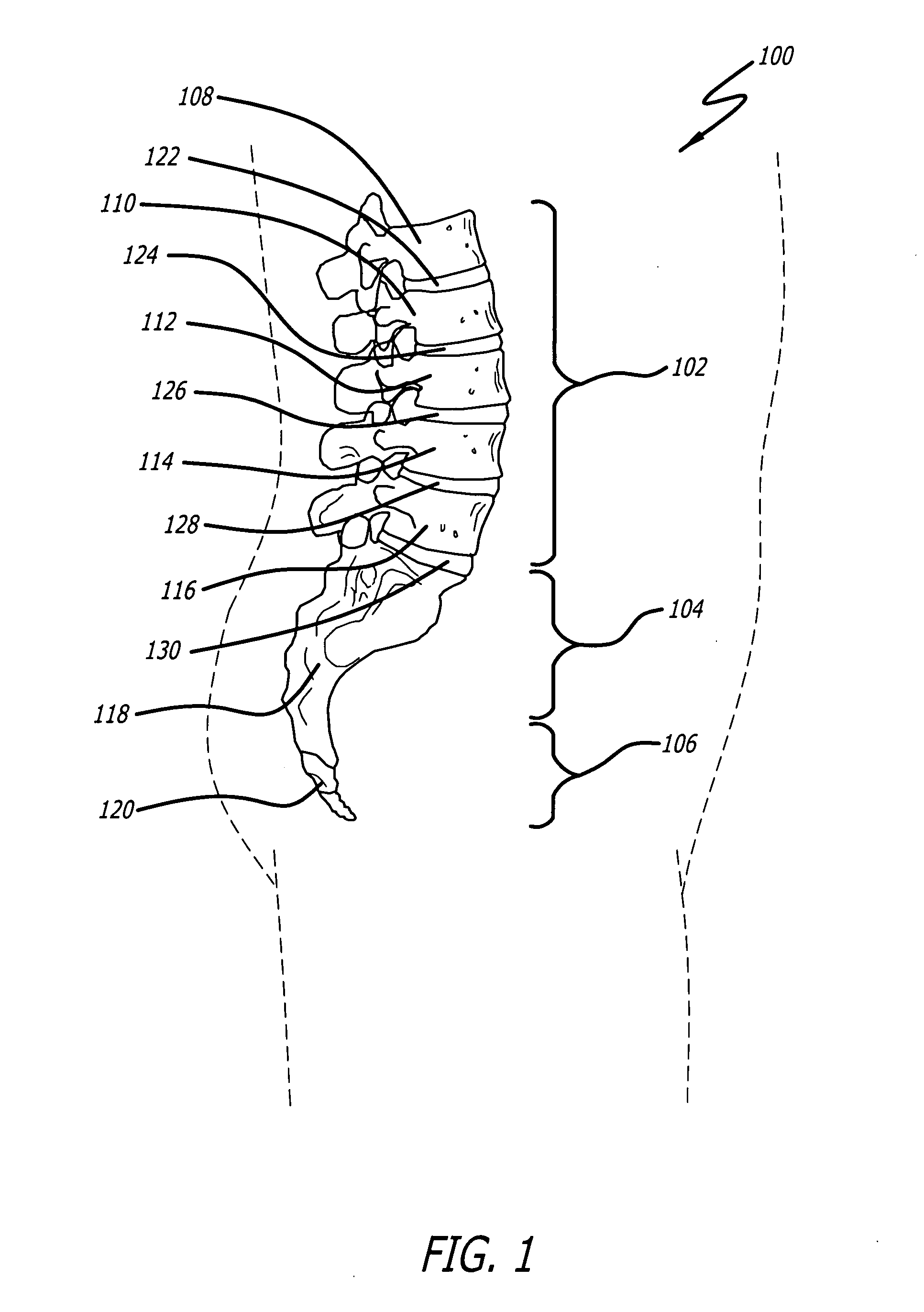
[0043]As shown in FIG. 1, a portion of a vertebral column, designated 100, is shown. As depicted, vertebral column 100 includes a lumbar region 102, a sacral region 104, and a coccygeal region 106. As is known in the art, vertebral column 100 also includes a cervical region and a thoracic region....


PUM


Abstract

A method is disclosed for increasing the stiffness of an intervertebral disc between vertebral bodies. The method includes providing a syringe with a needle approximately in the range of 16 to 25 gauge; providing a material having a first stage with a first viscosity adapted to flow through the needle, the material having a second stage with a second viscosity greater than the first viscosity, the second stage material having a stiffness in a range of 1.0-5.0 MPa; testing the annulus fibrosus of the disc to ensure that the annulus fibrosus has sufficient continuity so as to retain the first flowable stage material when subsequently injected into the disc; inserting the needle into the annulus fibrosus; injecting the first stage material into the disc; and permitting the first stage material to become the second stage material so as to form a load bearing implant in the disc.

Description

BACKGROUND OF THE INVENTION[0001]1. Field of the Invention[0002]The present invention relates generally to intervertebral disc reconstruction or repair methods. More specifically, the present disclosure relates to a method for increasing the stiffness of an intervertebral disc between adjacent vertebral bodies of a spine.[0003]2. Background of the Invention[0004]In human anatomy, the spine is a generally flexible column that can take tensile and compressive loads. The spine also allows bending motion and provides a place of attachment for keels, muscles and ligaments. Generally, the spine is divided into three sections: the cervical spine, the thoracic spine and the lumbar spine. The sections of the spine are made up of individual bones called vertebrae. Also, the vertebrae are separated by intervertebral discs, which are situated between adjacent vertebrae.[0005]The intervertebral discs function as shock absorbers and as joints. Further, the intervertebral discs can absorb the comp...

Claims


Application Information

Patent Timeline
IPC IPC(8): A61M31/00
CPCA61F2/442A61F2002/30075A61F2210/0085A61F2002/444A61F2210/0061A61F2002/30583
Inventor CRANDALL, DENNIS G.SIMONTON, T. ANDREWHADDOCK, SEAN M.
Owner WARSAW ORTHOPEDIC INC
Why Eureka
Try Eureka