Method and Apparatus for Continuously Injecting Fluid in a Wellbore While Maintaining Safety Valve Operation

a technology of safety valve and wellbore, which is applied in the direction of wellbore/well accessories, drilling casings, drilling pipes, etc., can solve the problems of obstructing the deployment of capillary tubing strings to subterranean production zones, affecting the safety of affecting the safety of the wellbore. , to achieve the effect of enhancing a certified wrscssv and revealing the operation of the safety valv

Active Publication Date: 2008-11-06
BAKER HUGHES INC
View PDF12 Cites 39 Cited by
  • Summary
  • Abstract
  • Description
  • Claims
  • Application Information

AI Technical Summary

Benefits of technology

[0027]The present invention further discloses a method of enhancing a certified WRSCSSV by connecting an upper capillary tube to a locking mandrel, connecting the locking mandrel to an upper adapter, connecting the upper adapter to a WRSCSSV and a bypass passageway, connecting the WRSCSSV to a lower adapter, and connecting the bypass passageway or pathway to the lower adapter. In addition, a spacer tube containing an injector and receptacle can be inserted between the locking mandrel and upper adapter. The spacer tube can also include a bypass passageway, which can simply be a capillary tube. A check valve can be installed on the lower adapter to prevent flow from the wellbore into the injection tubing. A capillary tube can also be installed on the check valve to provide deeper injections.
[0028]In another e

Problems solved by technology

Without a safety valve, a sudden increase in downhole pressure can lead to catastrophic blowouts of production and other fluids into the atmosphere.
Various obstructions exist within strings of production tubing in subterranean wellbores.
Valves, whipstocks, packers, plugs, sliding side doors, flow control devices, landing nipples, and dual completion components can obstruct the deployment of capillary tubing strings to subterranean production zones.
Particularly, in circumstances where stimulation operations are to be performed on non-producing hydrocarbon wells, the obstructions stand in the way of operations that are capable of obtaining continued production out of a well long considered “depleted.” Most depleted wells are not lacking in hydrocarbon reserves, rather the natural pressure of the hydrocarbon-producing zone is insufficient to overcome the hydrostatic pressure or head of the production column.
Often, secondary recovery and artificial lift operations will be performed to retrieve the remaining resources, but such operations are often too complex and costly to be performed on a well.
However, obstructions in a producing well often stand in the way to deploying an injec

Method used


Image

  • Method and Apparatus for Continuously Injecting Fluid in a Wellbore While Maintaining Safety Valve Operation
  • Method and Apparatus for Continuously Injecting Fluid in a Wellbore While Maintaining Safety Valve Operation
  • Method and Apparatus for Continuously Injecting Fluid in a Wellbore While Maintaining Safety Valve Operation

Examples


Embodiment Construction

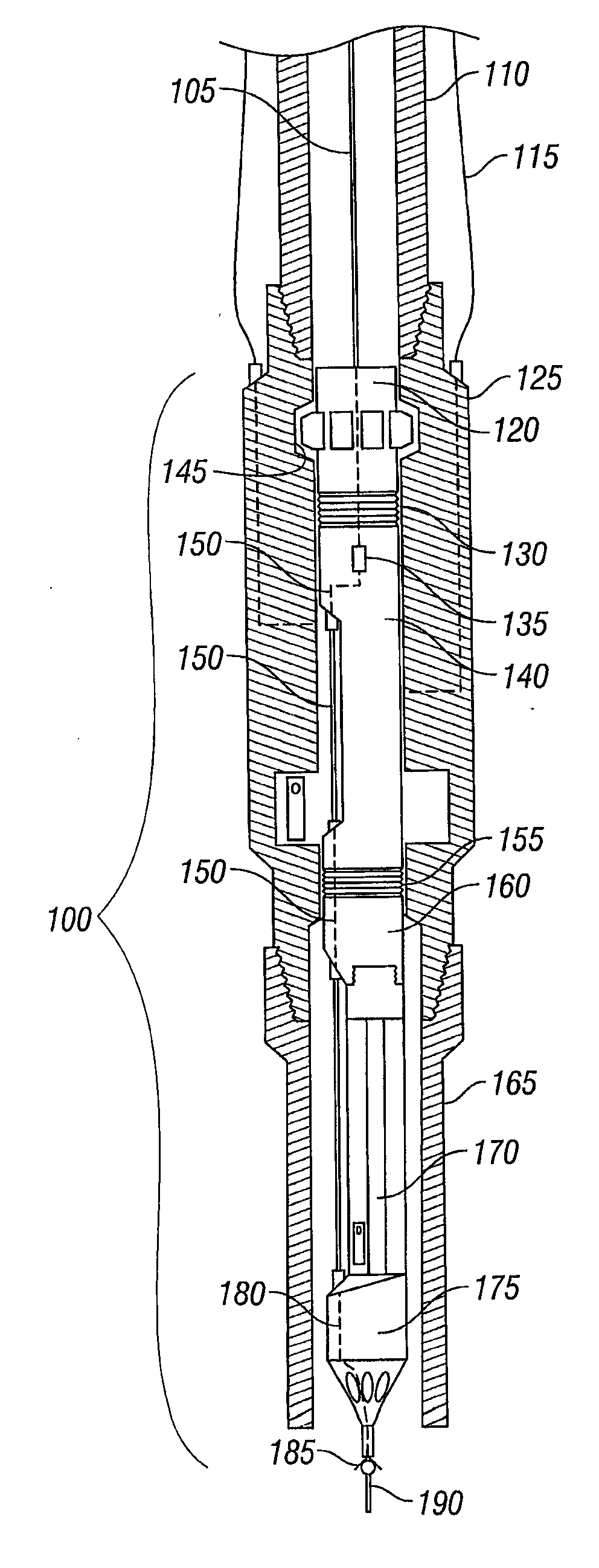
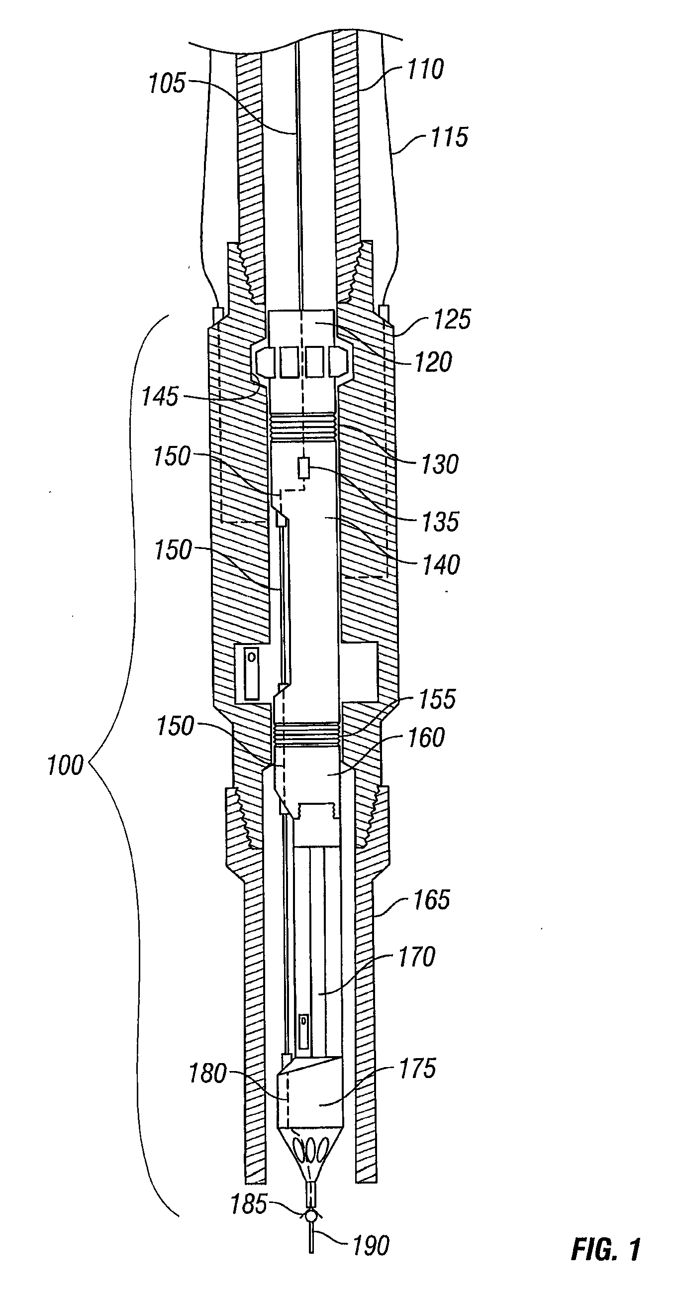
[0042]Referring initially to FIG. 1, one embodiment of a kit for enhancing a wireline retrievable surface controlled subsurface safety valve (“WRSCSSV”) 170 is shown installed. An enhanced wireline retrievable surface controlled subsurface safety valve (“enhanced WRSCSSV”) 100 kit can include an upper adapter 160, a lower adapter 175, and a bypass passageway 150 extending between the upper 160 and lower 175 adapters to maintain operability of the WRSCSSV 170. Although not shown, a seal, for example packing, can be included on either or both of upper 160 and lower 175 adapters to seal the enhanced WRSCSSV 100 to the bore of a tubular housing said valve. A packing can seal the enhanced WRSCSSV 100 to the bore of the tubular, for example, production tubing, so that fluid flow is routed through the bore of the WRSCSSV 170 while the bypass passageway 150 allows fluidic communication independent of the position of a closure member of the WRSCSSV 170.

[0043]An upper capillary tube 105 can b...


PUM


Abstract

A kit for converting an existing wireline retrievable surface controlled subsurface safety valve (170, 270, 370) into a bypass passageway apparatus (100) allowing the injection of production-enhancing fluid into a wellbore while maintaining the operation of the closure member (374). Bypass passageway (280) can extend between upper (260) and lower (275) adapters external to the existing wireline retrievable surface controlled subsurface safety valve (270) to allow fluid injection bypass thereof. Conversion kit can include a tubing string hanger to suspend a velocity tubing string (407, 507), a gas lift valve (475) for gas lift operations, a locking mandrel (220), and/or a spacer tube (240).

Description

CROSS-REFERENCE TO RELATED APPLICATION[0001]This application claims the benefit of provisional application U.S. Ser. No. 60 / 595,138 filed Jun. 8, 2005.BACKGROUND OF THE INVENTION[0002]Subsurface valves are typically installed in strings of tubing deployed to subterranean wellbores to prevent the escape of fluid, from one production zone to another and / or to the surface. The application of the present invention relates to all types of valves, and for the purposes of illustration in this disclosure is directed, as an example, to safety valves used to shut in a well in the absence of continued hydraulic pressure from the surface. This example should not be used to limit the scope of the disclosure for non safety valve applications which may be readily apparent from the disclosure made herein to a person having ordinary skill in this art.[0003]Without a safety valve, a sudden increase in downhole pressure can lead to catastrophic blowouts of production and other fluids into the atmosphe...

Claims


Application Information

Patent Timeline
IPC IPC(8): E21B43/12
CPCE21B33/068E21B34/105E21B41/02E21B43/122
Inventor HILL, THOMAS G.MAILAND, JASON C.MCGAVERN, CECIL G.SIDES, WINFIELD M.BOLDING, JEFFREY L.
Owner BAKER HUGHES INC
Why Eureka
Try Eureka