

System and Method for Supplying an Ink to a Reciprocating Printhead in an Inkject Apparatus
- Summary
- Abstract
- Description
- Claims
- Application Information
AI Technical Summary
Benefits of technology
Problems solved by technology
Method used
Image

Examples
first embodiment
Printing Mode
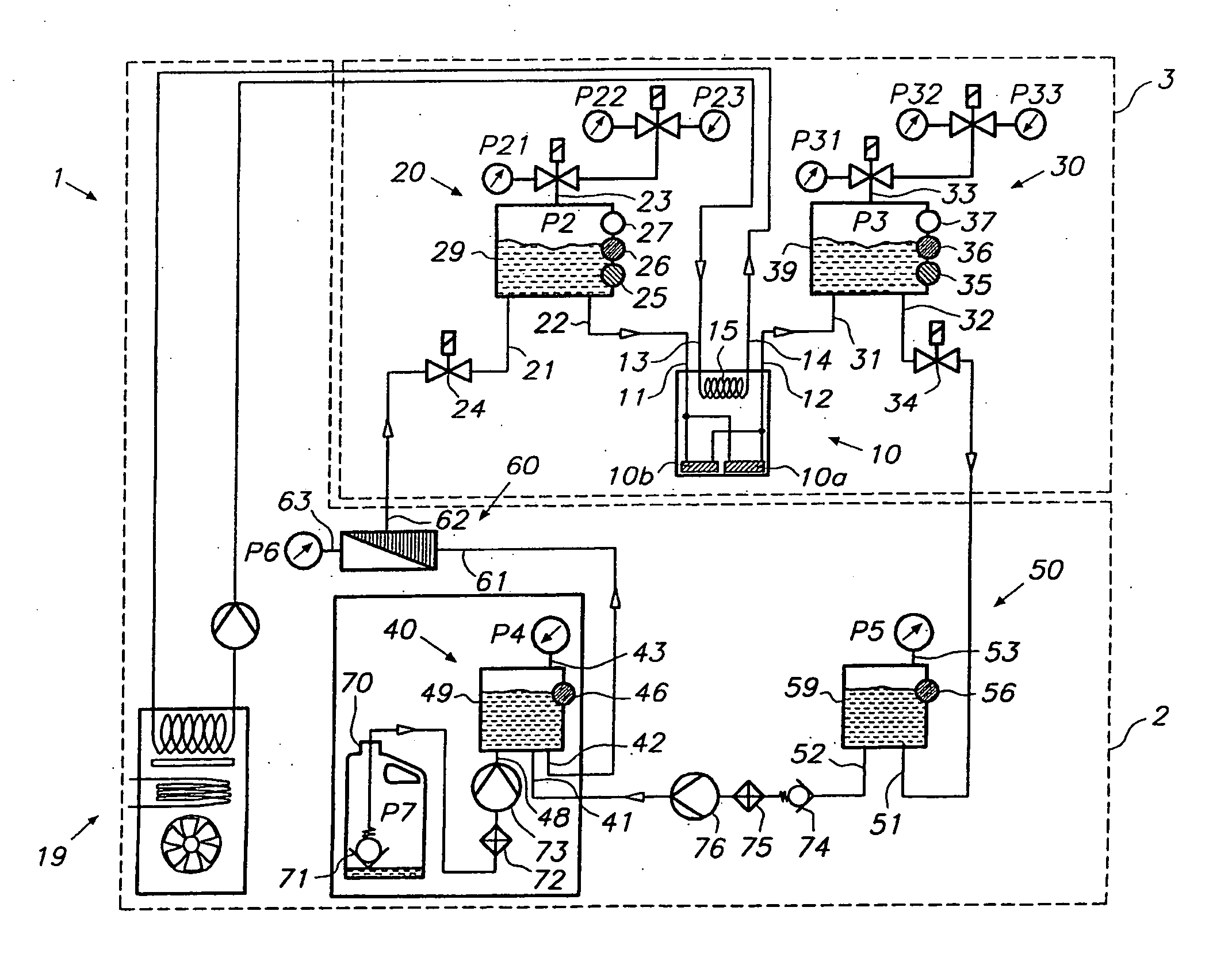
[0039]The operation of the embodiment according to FIG. 1 in normal printing mode is now being described. An ink flow through the printhead 10 is realized by establishing a pressure difference between the pressure P2 in the supply subtank 20 and the pressure P3 in the return subtank 30. These pressures are applied via pressure connection 23 on the supply subtank 20 respectively pressure connection 33 on the return subtank 30. In order to create a positive flow from the supply subtank 20 through the printhead 10 and into the return subtank 30, the pressure in the supply subtank 20 is controlled at a slightly higher value than the pressure in the return subtank 30. The ink flow rate through the printhead is controllable via pressure difference P3−P2 but depends also on the hydraulic resistance of the fluid conducts to and from the printhead as well as the flow rate of ink through these conducts, and the hydraulic resistance internally in the printhead. In practice a press...
first embodiments
Non-Printing Modes
[0048]The pressure P2 in the supply subtank 20 can be selected from at least three preset values P21, P22 and P23 that correspond to different operating conditions of the printhead 10. These preset pressure values for the supply subtank 20 cooperate with a parallel set of preset values P31, P32, P33 for the pressure P3 in the return subtank 30. A first operating condition of the printhead corresponds with a normal printing condition that has been described previously. For this purpose a set of valves (see FIG. 1) could be operated to link preset values P21 and P31 to their respective subtank.
[0049]A second operating condition of the printhead may be a purging operation, wherein the pressures applied to the nozzles is such that ink is flows out of the nozzles without actuating the nozzles. For a purging operation, equal positive pressures are applied to the supply subtank 20 and the return subtank 30. In this case there is no through-flow in the printhead 10 and all...
PUM
 Abstract
Description
Claims
Application Information