Strape glove

a glove and strap technology, applied in the field of gloves, can solve the problems of energy loss in the area, no improvement of hand fatigue associated with repetitive motion, and the web deflects very little during use, so as to improve the leverage and support of such items, improve the control and striking force of hand-held tools, and improve the control and striking for

Active Publication Date: 2008-11-13
DUBY DANTE
View PDF8 Cites 12 Cited by
  • Summary
  • Abstract
  • Description
  • Claims
  • Application Information

AI Technical Summary

Benefits of technology

[0025]A glove that improves control and striking force of a handled tool such as a hammer, ax, baseball bat, or the like by improving the leverage and support of such an item when held. In addition to the improved control and striking force, the glove also improves tool head acceleration, energy transfer, and grip, while reducing hand fatigue and vibration shock.

Problems solved by technology

This strap web deflects very little during use due to its non-elastic nature.
And, although some gloves can provide for an increased grip with less slippage, they do nothing to improve hand fatigue associated with a repetitive motion.
Even in cases where padding is added between the thumb and index finger, there is energy lost in that area when the muscles of the hand flex while trying to stabilize a held item.
Therefore, no usable leverage advantage was gained.
First, the elastic material could not resist an impact force applied to a handled tool when striking another object.
First, the sheath / hinge arrangement does not allow a person to grasp an object with a handle, or rather grasp it with any ability to control it.
Second, because the sheath materials must be fairly rigid to protect the finger and thumb from the hammer blows, tool use would be difficult.
Also, the design does not appear to be adjustable for different finger and thumb sizes, only allows for a single finger and thumb, and provides no additional gripping ability.
If the loop is on the finger, with the strap wrapping around the thumb, any impact forces would be absorbed through the strap at its anchor point on the wrist, possibly causing wrist injury, but providing very little leverage advantage because of the long length of the strap.

Method used


Image

  • Strape glove
  • Strape glove
  • Strape glove

Examples


Embodiment Construction

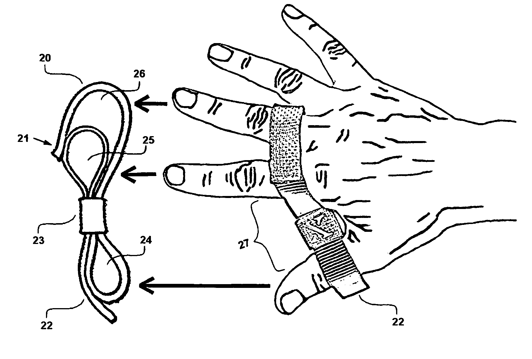
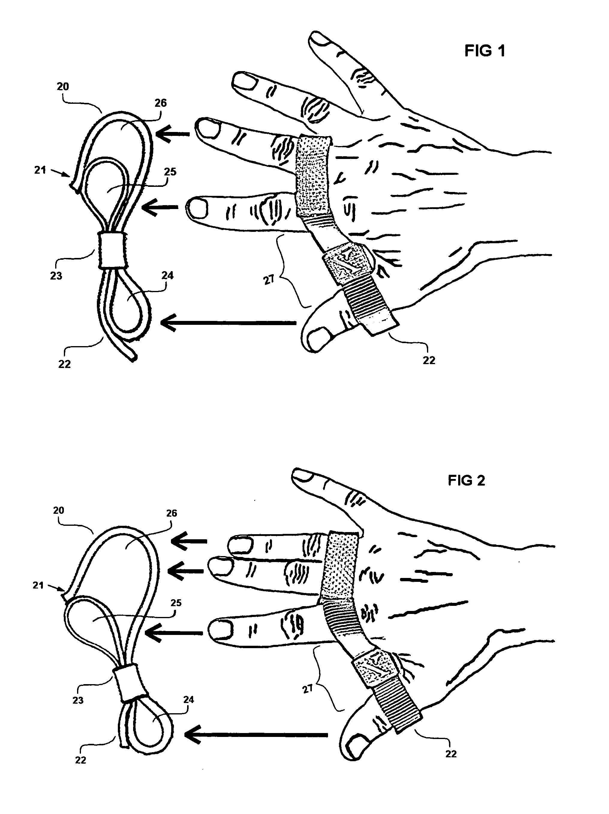
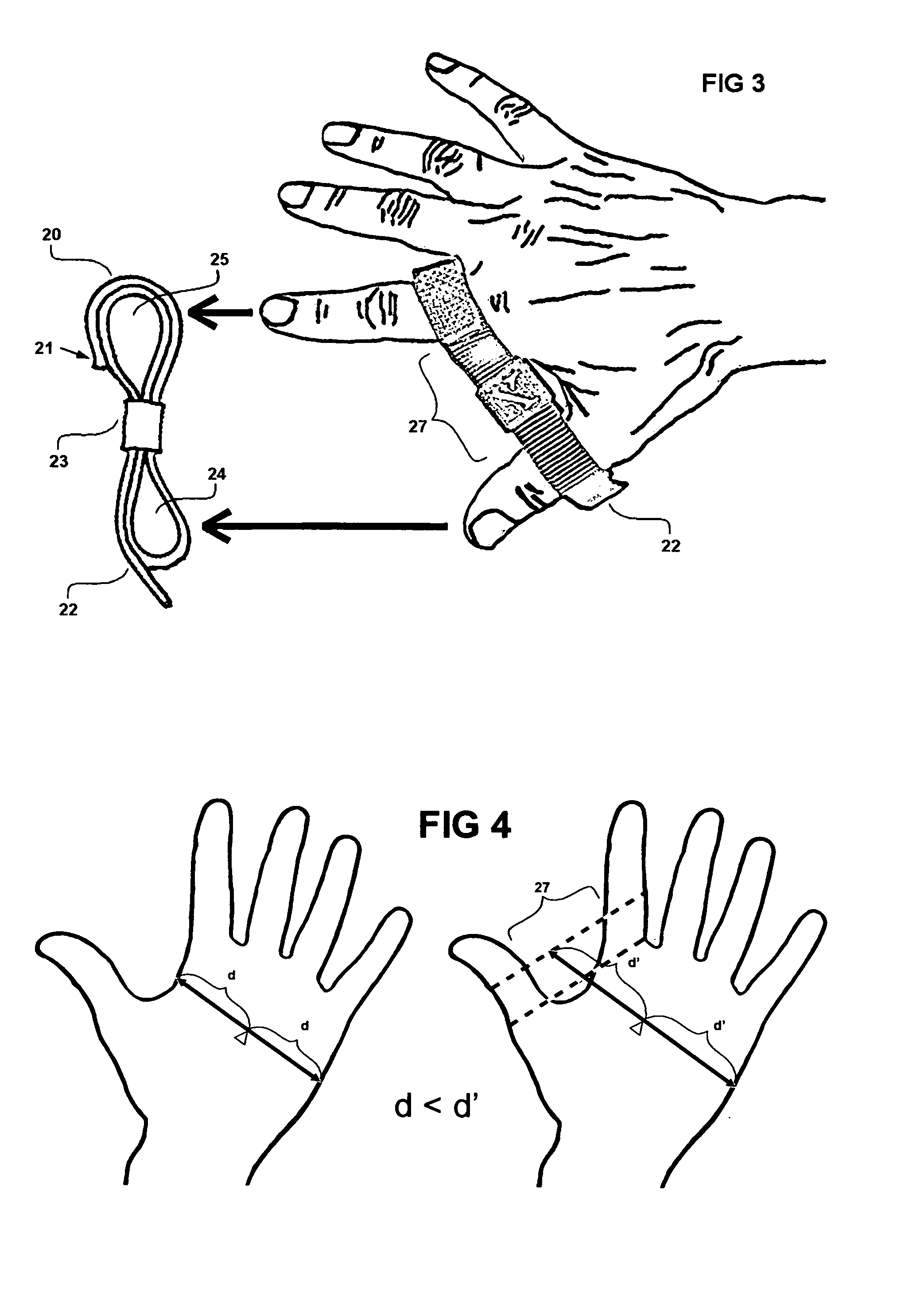
[0035]Referring to the drawings for a more detailed explanation of the preferred form of the invention, FIG. 1 shows the most common configuration of the glove both from the side view and a functional view. This is called the standard two finger configuration since two fingers and a thumb are used. Most people with normal size hands and fingers will find this configuration to be the most comfortable. In the side view significant areas of the glove are listed. The narrow strap material, 20, is folded (as indicated in FIG. 7-FIG. 10), attached to itself at point 21, and held together with the contact friction loop 23. This forms the glove with three distinct loops, the thumb hole 24, first finger hole 25 and second finger hole 26. The pull-tab adjustment 22 is used to control the span between the thumb and fingers, known as the strap web 27, for accommodating different tool handle thicknesses, and also to adjust the size of all three holes to accommodate different hand and finger size...


PUM


Abstract

A glove made from narrow strap material. Glove advantages when used with a striking tool: improved control, improved striking force, improved tool head acceleration, improved energy transfer, reduced hand fatigue, improved grip, and reduced vibration shock. It can be configured for 1, 2, 3 or 4 fingers plus the thumb. The glove forms a web between the thumb and fingers. The width of the web and the tightness of fit on the thumb and fingers is controlled by a single pull-tab type of adjustment. The adjustment is secured by a contact friction loop which increases in friction during impact force use. The glove can be worn on a bare hand or over the top of a more conventional type of glove while still providing the same advantages.

Description

[0001]This is a continuation in part of application Ser. No. 11 / 681,054 filed Mar. 1, 2007.BACKGROUND OF THE INVENTION[0002]The present invention relates to gloves, more specifically to a special type of glove which allows the wearer to transfer greater impact force energy from a striking tool, with a handle, to an object being struck. Generally gloves provide protection for the hand and some may improve grip but virtually none of them are designed to improve mechanical advantage compared with bare handed use. Whereas the present invention is designed specifically for: improved control, improved striking force, improved tool head acceleration, improved energy transfer, reduced hand fatigue, improved grip, and reduced vibration shock.[0003]One object of the present invention is to improve the control of a striking tool such as a baseball bat, hammer, ax, tennis racket, or similar items with handles, by increasing support and stability of the grasped item. The present invention provid...

Claims


Application Information

Patent Timeline
Patent Type & Authority Applications(United States)
IPC IPC(8): A41D13/08A41D19/00
CPCA41D19/01582A63B71/143A63B71/148
Inventor DUBY, DANTE
Owner DUBY DANTE
Why Eureka
Try Eureka