Reciprocating Saw and Attachments

a reciprocating saw and attachment technology, applied in the field of reciprocating saw and attachment, can solve the problems of user's cutting accuracy, less control, and inability to easily make such cuts with a reciprocating tool, and achieve the effect of quick interchange, stability and strength

Inactive Publication Date: 2008-11-13
RITTER JON +1
View PDF0 Cites 29 Cited by
  • Summary
  • Abstract
  • Description
  • Claims
  • Application Information

AI Technical Summary

Benefits of technology

[0011]The present invention is an attachment for reciprocating tools that allows blades, sanders, or any other device associated with a reciprocating tool to be quickly interchanged. The present invention has spaces common devices for reciprocating tools in different but parallel plane to the plane of the reciprocating tool. Thus, the user can access areas typically unreachable because with the present invention, the user can hold the reciprocating tool's body in a different plane than the device attached to the reciprocating tool. The present invention preferably has a 45 degree angle shift between the plane of the reciprocating tool and tire plane of the device attached to the reciprocating tool. The angle provides a good blend of offset distance, structural integrity, and extension of the device ahead of the reciprocating tool.
[0012]Alternative embodiments of the present invention provide for rotation at the point where the reciprocating tool's body attaches to holder for a device attached to a reciprocating tool, such that the holder for the device attached to the reciprocating tool rotates for ease of use in accessing work areas. Additional embodiments of the present invention provide for rotation at the point where the device attached to a reciprocating tool attaches to blades, sanders, or any other device associated with a reciprocating tool—such that the device attached to a reciprocating tool rotates for ease of use in accessing work areas. Further embodiments of the present invention provide means to extend the reach of blade attachment with stability and strength, additional sanding paddles and a multi tool attachment. The extension may be anywhere from 2 inches to 10 feet, however the preferred length is 2 inches to 2 feet. The sanding paddles, of all shapes and sizes, are preferably made of memory plastic and that has the capability to attach sandpaper to at least one side via one of many conventional fastening means, such as glue, hook and loop or adhesive tape.

Problems solved by technology

For example, if a user wants to use a reciprocating tool to cut a two-inch by two-inch section in a dry wall area so that the two inch by two inch section is adjacent to a floor, the user cannot easily do so with a reciprocating tool.
Because the saw blade extends out of the center front of the reciprocating tool, and the reciprocating tool has a bulky mass, the user can only make such a cut into the drywall at an angle away from ninety degrees.
Varying from a perpendicular point of attack, the user's cut is less reliable, less controlled, and encroaches into the drywall unevenly.
Restated, the problem is that the user cannot possibly position the reciprocating tool perpendicular to the drywall because the housing of the reciprocating tool must remain above the floor.
In the past, users have attempted to create attachments capable of making cuts near an object while maintaining a perpendicular point of attack; however, such attachments have been either not rigid enough in order to effectuate a straight cut (that is, the saw attachments bend under the pressure of the saw attachments entering the drywall), have been too rigid thereby preventing the user from completing the cut all the way into a corner (that is, the saw attachments cannot be adjusted or interchanged as access to points of attack vary), or have been so complicated that they would break—and when broken, would be very expensive to fix.
Further, Atkinson's blade holder does not offer any extension of the blade forward, so that the power saw can remain a greater distance from the cut while cutting.
However, Happe's device uses a guide rod, which shortens the cut of the blade and does not allow the blade to be as flexible as desired.
Further, Happe's device does not allow for different and varied blade placements and offsets.
Although Mineck's offset blade adapter does allow for the blade to be placed in more then one position, one of which is that of the flush cut, Mineck's adapter does so through a complicated device that, once broken, is expensive to replace.
Further, Mineck's adapter does not allow for different and varied blade placements and offsets, and does not extend the distance between the blade and the reciprocating tool.

Method used


Image

  • Reciprocating Saw and Attachments
  • Reciprocating Saw and Attachments
  • Reciprocating Saw and Attachments

Examples


Embodiment Construction

)

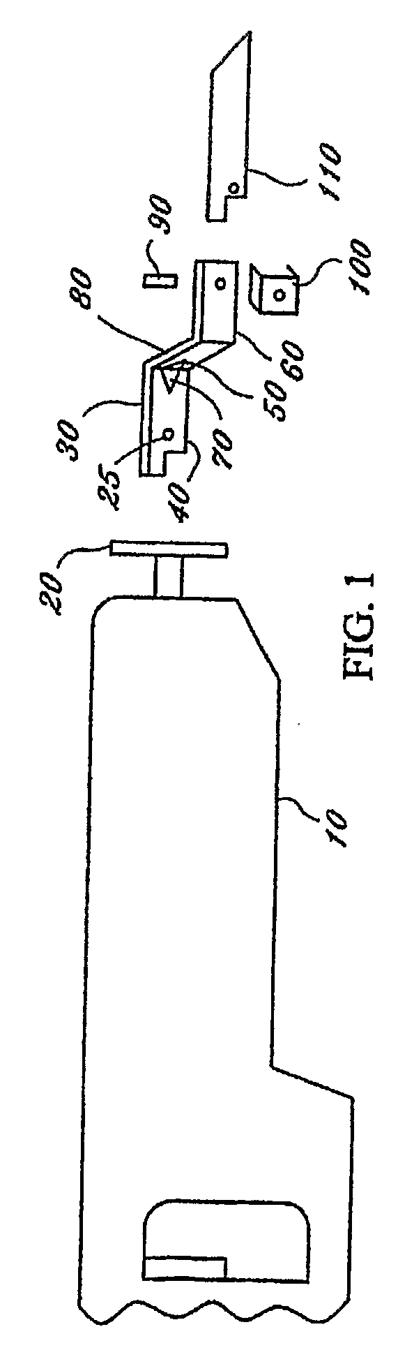
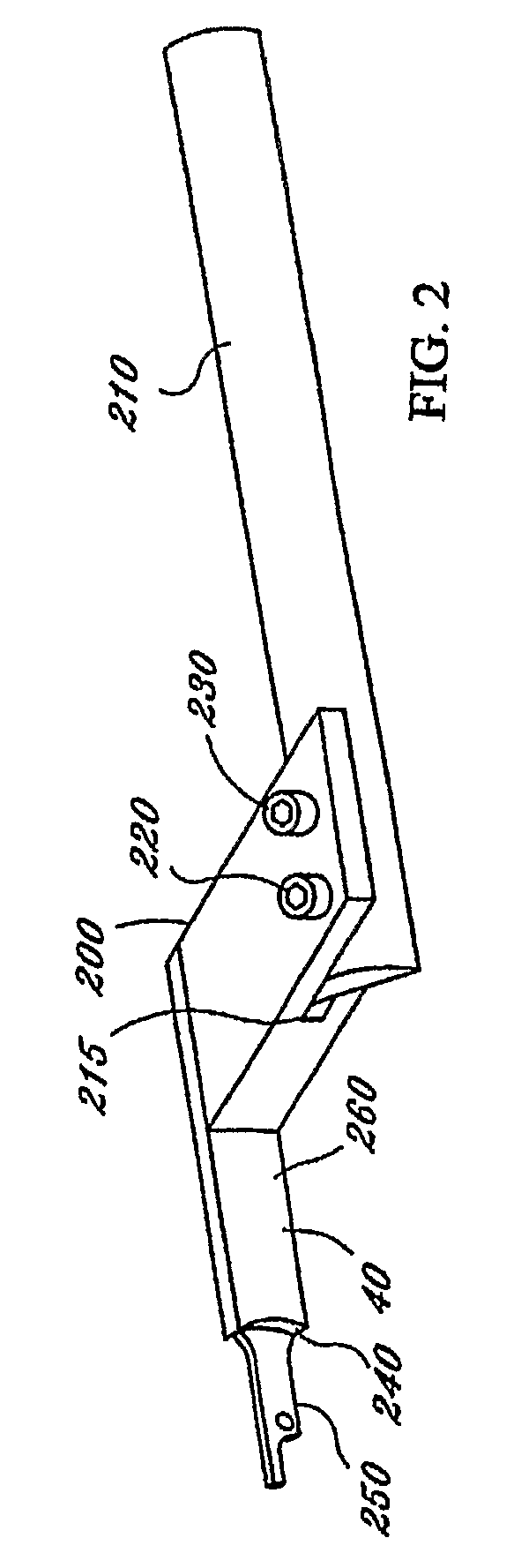
[0042]As seen in the attached drawings, the present invention is designed to be used with any power driven saw (10) having a reciprocating drive member (20). The present invention has an offset adapter (30) made up of a first, second, and third metal planes (40, 50, 60), two angle braces (70, 80), a conventional set screw (90), preferably a conventional screw that can be tightened or loosened by user with hands, and a set screw receiving member (100).

[0043]The first straight metal plane (40) is designed to insert into the reciprocating drive member (20) and has the standard hole (25) used for locking any reciprocating saw blade into a reciprocating drive member (20). The second straight metal plane (50) is disposed anywhere from 90-degrees to 45 degrees from the first metal plane (40), and the second straight metal plane (50) is correspondingly attached to the third metal plane (60) anywhere from 90-degrees to 45 degrees from the third metal plane (60).

[0044]The first metal plane (...


PUM

PropertyMeasurementUnit
angleaaaaaaaaaa
lengthaaaaaaaaaa
lengthaaaaaaaaaa

Abstract

A simple attachment for a reciprocating tool that will effectuate the ability to do a flush cut in an inexpensive and simple manner which is neither' too ligid, nor not rigid enough. This is effectuated by providing an insert, which fits into the reciprocating tool in the same fashion as a regular' blade. The present invention then offsets the placement of a blade, sander, file, or' other 1 tool by as many inches as wished by the user 1. The blade, sander, file, or other tool is held rigid through the use of a 45 degree bracket spanning the distance from the original plane to the offset plane, or via a single or compound trapezoid design.

Description

[0001]Priority is hereby claimed to U.S. patent application No. 60 / 481,864 filed on Jan. 6, 2004, as well as PCT / US04 / 09432 Mar. 30, 2004FIELD OF THE INVENTION[0002]The present invention relates to an attachment for reciprocating tools, such as reciprocating saws. More particularly, the present is an offset attachment that permits a reciprocating tool to be fit with a variety of blades, sanders, and the like to attack a point from an offset angle.BACKGROUND OF THE INVENTION[0003]Conventional reciprocating tools allow the user to attack a point straight on, or in other words, in a direct line from the tip of the reciprocating tool to the point. While a typical blade can be affixed in the center of the reciprocating tool, the body of the reciprocating tool oftentimes interferes with the surfaces around a point of attack.[0004]For example, if a user wants to use a reciprocating tool to cut a two-inch by two-inch section in a dry wall area so that the two inch by two inch section is adj...

Claims


Application Information

Patent Timeline
Patent Type & Authority Applications(United States)
IPC IPC(8): B27B19/00B27B23/00B23D49/16B23D51/10B27B3/12
CPCB23D49/167B23D51/10
Inventor RITTER, JONRITTER, REBECCA
Owner RITTER JON
Why Eureka
Try Eureka