
Air conditioning apparatus

a technology of air conditioning and air intake, which is applied in the direction of light and heating apparatus, machine operation mode, refrigeration components, etc., can solve the problems of increased cost, increased risk of liquid sealing, and increased cost of motor-actuated expansion valves, so as to prevent abnormal pressure increase and excellent reliability

Inactive Publication Date: 2008-11-13
SANYO ELECTRIC CO LTD +1
View PDF0 Cites 11 Cited by
  • Summary
  • Abstract
  • Description
  • Claims
  • Application Information

AI Technical Summary

Benefits of technology

[0010]An object of the present invention is to provide an air conditioning apparatus capable of preventing refrigerant pressure from being abnormally increased because of a liquid-sealed state, and excellent in reliability.

Problems solved by technology

However, a large-sized motor-actuated expansion valve is expensive and leads to an increase in the cost, and hence an air conditioning apparatus using two motor-actuated expansion valves connected in parallel with each other is known (for example, Jpn. Pat. Appln. KOKAI Publication No. 2003-214729).
However, when the compressor is stopped, and each of the motor-actuated expansion valves is fully closed, a liquid-sealed state where the refrigerant flow path on the outdoor heat exchanger side is liable to occur.
If this liquid-sealed state occurs, there is the possibility of the pressure of the refrigerant collected there being abnormally increased because of an increase in the outside air temperature.
If the pressure of the refrigerant is abnormally increased, the components of the refrigerating cycle have been damaged in the worst case.

Method used


Image

  • Air conditioning apparatus
  • Air conditioning apparatus
  • Air conditioning apparatus

Examples


Embodiment Construction

[0020]An embodiment of the present invention will be described below with reference to the accompanying drawings.

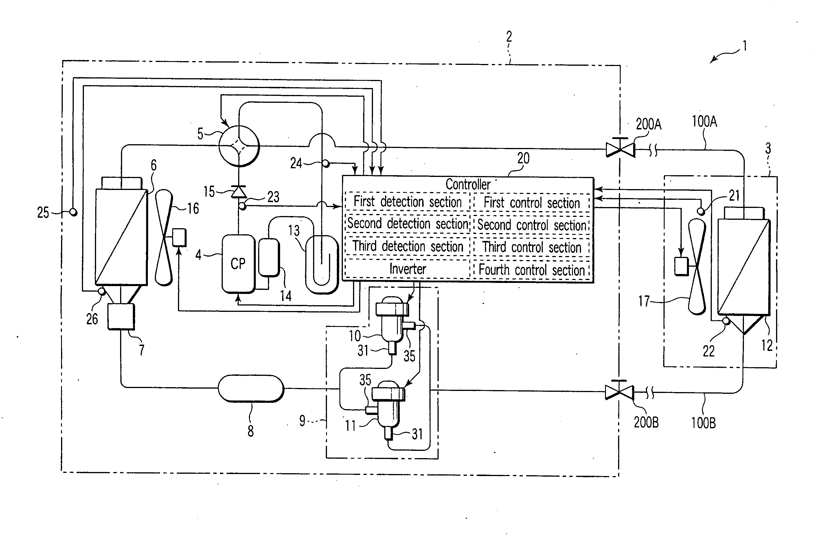
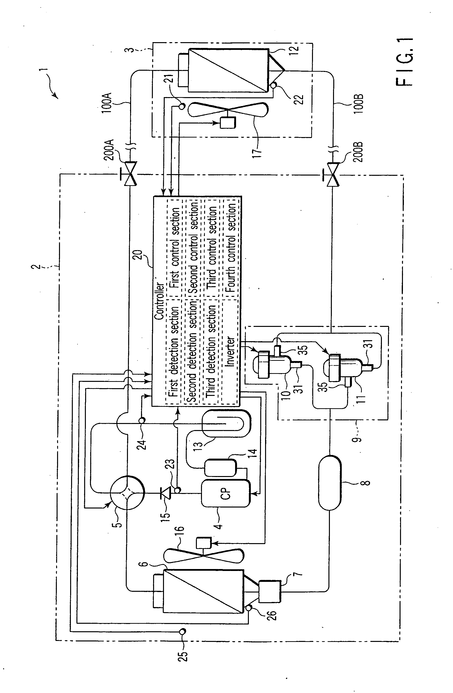
[0021]As shown in FIG. 1, an air conditioning apparatus 1 is provided with an outdoor unit 2 and an indoor unit 3. The outdoor unit 2 is provided with a gas pipe service valve 200A and a liquid pipe service valve 200B. The indoor unit 3 is connected to the service valves 200A and 200B through a gas pipe 100A and a liquid pipe 100B.

[0022]The outdoor unit 2 and the indoor unit 3 are provided with a heat-pump-type refrigerating cycle. This refrigerating cycle includes at least one compressor 4 for sucking a refrigerant, compressing the refrigerant, and discharging the compressed refrigerant, and at the time of cooling, a cooling cycle in which the refrigerant discharged from the compressor 4 is passed through a backflow check valve 15, a four-way valve 5, an outdoor heat exchanger 6, a flow divider 7, a receiver tank 8, a pressure reducing device 9, the liquid pipe service v...


PUM


Abstract

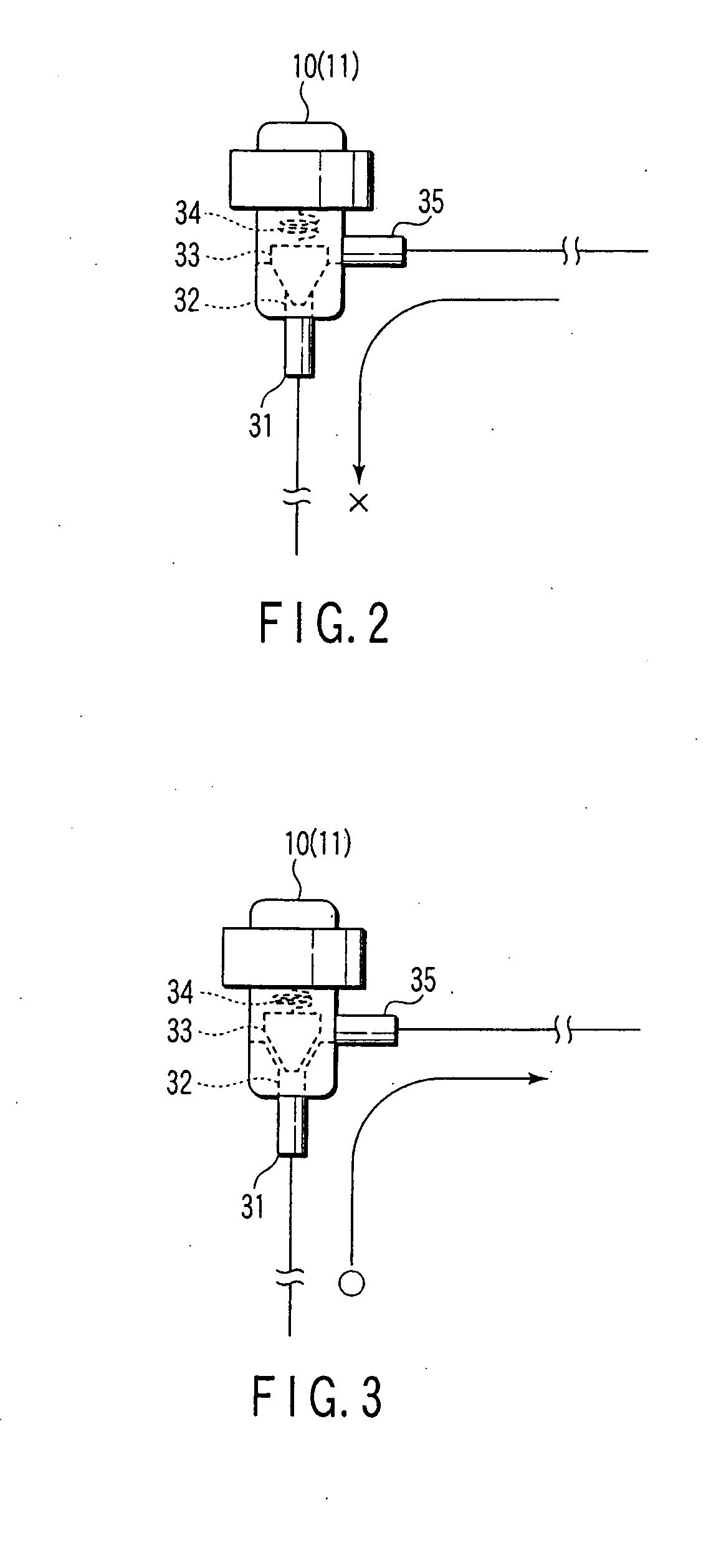
A first motor-actuated expansion valve and a second motor-actuated expansion valve which are connected in parallel with each other in back-to-back connection are provided between an outdoor heat exchanger and an indoor heat exchanger. In the first motor-actuated expansion valve, at the time of non-operation and full closure, when the refrigerant pressure on the indoor heat exchanger side is higher than the refrigerant pressure on the outdoor heat exchanger side by a predetermined value or more, the full closure is released by receiving the refrigerant pressure on the indoor heat exchanger side. In the second motor-actuated expansion valve, at the time of non-operation and full closure, when the refrigerant pressure on the outdoor heat exchanger side is higher than the refrigerant pressure on the indoor heat exchanger side by a predetermined value or more, the full closure is released by receiving the refrigerant pressure on the outdoor heat exchanger side.

Description

CROSS-REFERENCE TO RELATED APPLICATIONS[0001]This is a Continuation application of PCT Application No. PCT / JP2007 / 050908, filed Jan. 22, 2007, which was published under PCT Article 21(2) in Japanese.[0002]This application is based upon and claims the benefit of priority from prior Japanese Patent Application No. 2006-012201, filed Jan. 20, 2006, the entire contents of which are incorporated herein by reference.BACKGROUND OF THE INVENTION[0003]1. Field of the Invention[0004]The present invention relates to an air conditioning apparatus provided with a plurality of motor-actuated expansion valves.[0005]2. Description of the Related Art[0006]An air conditioning apparatus is provided with a refrigerating cycle in which a compressor, an outdoor heat exchanger, a pressure reducing device, an indoor heat exchanger, and the like are successively connected to each other by piping. As a refrigerant to be filled into the refrigerating cycle, the R410 refrigerant with high pressure is known. In...

Claims


Application Information

Patent Timeline
IPC IPC(8): F25B41/04F25B1/00F25B29/00
CPCF25B13/00F25B41/062F25B49/025F25B2313/02741F25B2313/0314F25B2313/0315F25B2341/0661F25B2500/27F25B2600/021F25B2600/21F25B2700/2104F25B2700/2106F25B2700/21151F25B2700/21152Y02B30/741Y02B30/70F25B41/385F25B41/35
Inventor TERASAKI, AKIRAOKITSU, KAZUTO
Owner SANYO ELECTRIC CO LTD
Learn More