Eureka AIR delivers breakthrough ideas for toughest innovation challenges, trusted by R&D personnel around the world.

Sheet metal section

a metal section and sheet metal technology, applied in the direction of metal working apparatus, etc., to achieve the effect of saving the over-lapping distance, less wear, and high production volum

Inactive Publication Date: 2008-11-13
SAAB AUTOMOBILE AB
View PDF9 Cites 1 Cited by
  • Summary
  • Abstract
  • Description
  • Claims
  • Application Information

AI Technical Summary

Benefits of technology

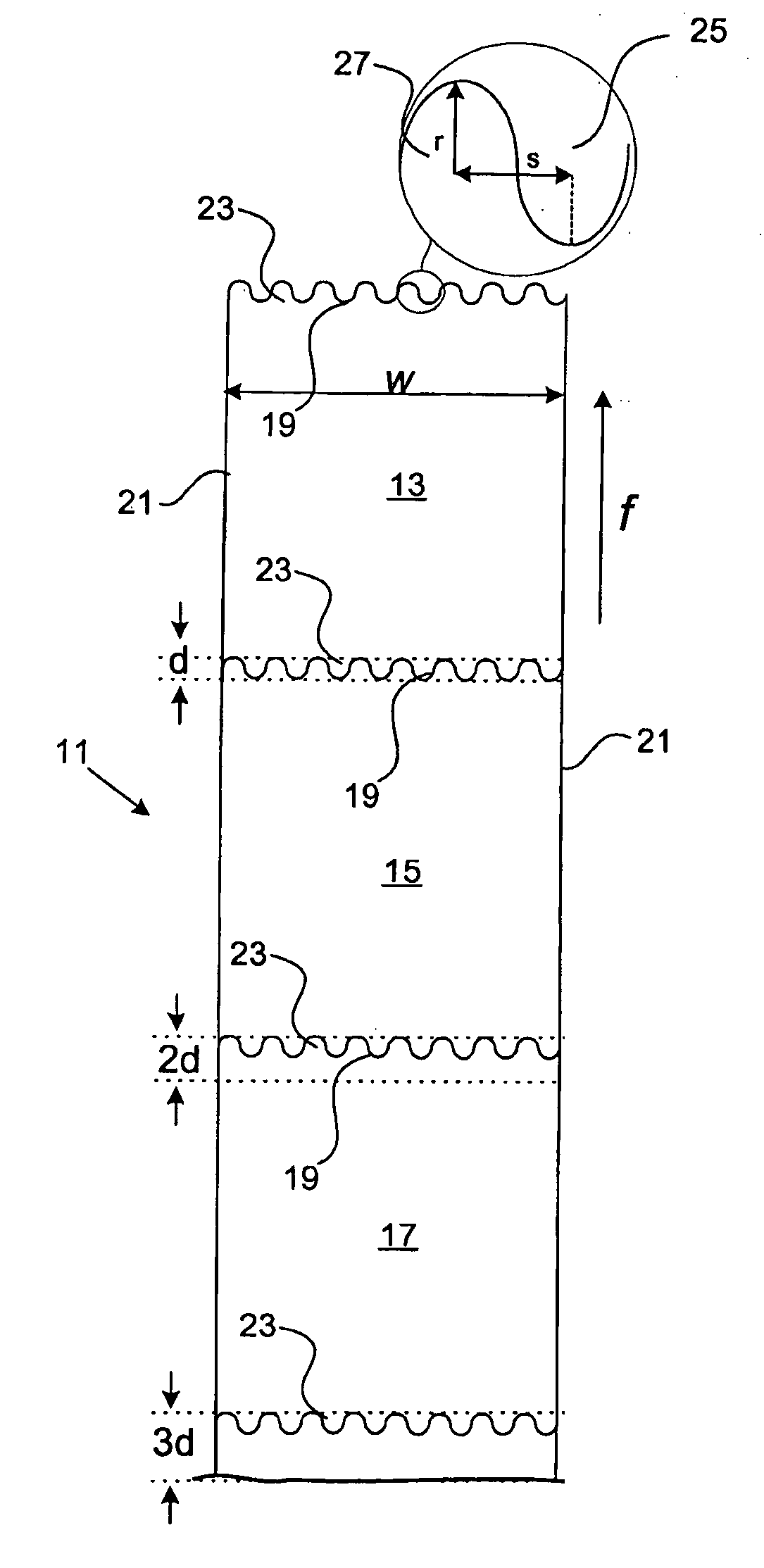
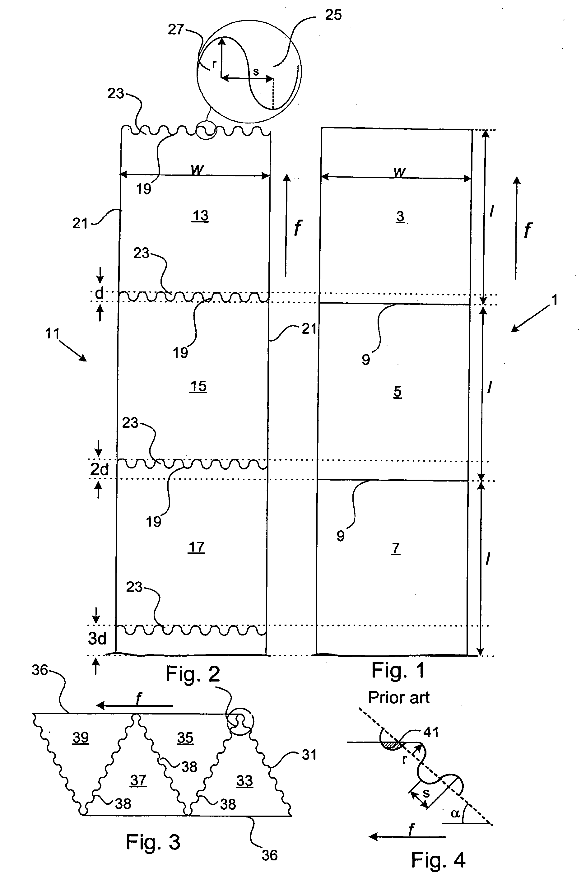
[0011]Due to the wave shape of the edge portions, sheet metal material is saved since less material need to be rejected. By means of the method it is possible to provide finite length sections having wave shaped edge portions of the same length as if the sections were provided with linear straight edge portions, at the same time as material is saved. The reason is that the wave shaped edge portions of two, in the feeding direction, consecutive sections overlap each other. Thus, for every cut a distance corresponding to the height of the wave shaped, i.e. the over-lapping distance is saved. When production volumes are high a lot of material may be saved.
[0012]Moreover, if the cutting step is followed by the step of firmly holding the wave shaped edge portions in a subsequent sheet metal section machining operation, e.g. a pressing operation, the holder tool will be subjected to less wear if the edge portions are wave shaped instead of linear. The reason is that when the edge portions are wave shaped the material can more easily deform during the strike of the pressing tool. When the edge portions are linear such deformation is not possible to the same extent, so instead the holder tool will absorb the corresponding deformation forces.
[0015]Suitably, the wave shape is sinusoidal. Hereby, tool manufacturing is simplified at the same time as a continuous, smooth cut is provided.

Problems solved by technology

When the edge portions are linear such deformation is not possible to the same extent, so instead the holder tool will absorb the corresponding deformation forces.

Method used


Image

  • Sheet metal section
  • Sheet metal section
  • Sheet metal section

Examples


Embodiment Construction

[0022]FIG. 1 shows a portion of a continuous strip 1 of sheet metal. A related art method for cutting such strips will now be described. The strip is fed out from a coil of sheet metal in the direction of arrow f (the coil itself is not shown, but it is understood that it should be located below the strip as positioned in the figure). The strip is to be cut into three finite length sections 3, 5, 7, each having a length l and a width w. When a length l of the strip 1 has been fed out from the coil, a not shown cutting tool cuts the continuous strip along a straight line 9 and separates the cut section 3 from the rest of the continuous strip 1. This cut section 3 is removed and yet a length l is fed out and yet a section 5 is cut off This procedure is repeated as many times as desired, and the cut off sections are ready for further machining.

[0023]FIG. 2 shows a portion of a continuous strip 11 of sheet metal. The method according to the invention for cutting such strips will now be ...


PUM

PropertyMeasurementUnit
heightaaaaaaaaaa
heightaaaaaaaaaa
heightaaaaaaaaaa

Abstract

A method of cutting a strip of sheet metal, including feeding out a continuous strip of sheet metal in a feeding direction, cutting the strip into a plurality of lengths, including making a wave shaped cut between each length and an adjacent length, wherein each of a forward edge and a following edge of each length include a plurality of waves, and selecting at least one of a radius of each of the plurality of waves and a spacing between adjacent ones of the plurality of waves based on a cutting angle, wherein the cutting angle is oblique with respect to the feeding direction.

Description

CROSS-REFERENCE TO RELATED APPLICATIONS[0001]This application is a divisional of U.S. patent application Ser. No. 10 / 708,259 filed on Feb. 20, 2004. The disclosure of the above application is incorporated herein by reference.BACKGROUND OF INVENTION [0002]1. Field of the Invention[0003]The present invention relates to a method for cutting a continuous strip of sheet metal into finite length sections. The invention also relates to such a finite length section.[0004]2. Description of Related Art[0005]In a variety of manufacturing industries sheet metal is used. The sheet metal normally arrives at the manufacturing industry stored in coils comprising a continuous strip of sheet metal. Coiled sheet metal facilitate transportation and can be purchased in a variety of lengths, widths, thickness and material. However, before the sheet metal can be further machined, the continuous strip must be cut into finite lengths. For this purpose, machines for shearing, slitting and sawing a continuous...

Claims


Application Information

Patent Timeline
Patent Type & Authority Applications(United States)
IPC IPC(8): B26D3/00B21D22/22B21D28/06B21D35/00
CPCB21D28/06B21D35/00Y10T83/0577
Inventor ANDERSSON, KURT
Owner SAAB AUTOMOBILE AB
Why Eureka
Eureka Blog
Learn More