
Gas delivery system with constant overpressure relative to ambient to system with varying vacuum suction

a gas delivery system and vacuum suction technology, applied in the direction of prosthesis, physical/chemical process catalysts, lighting and heating apparatus, etc., can solve the problems of high cost, contamination, and care to produce or condition sensitive or reactive materials, and achieve the effect of minimizing the pressure differential in the system

Active Publication Date: 2008-11-13
UMICORE AG & CO KG +1
View PDF99 Cites 61 Cited by
  • Summary
  • Abstract
  • Description
  • Claims
  • Application Information

AI Technical Summary

Benefits of technology

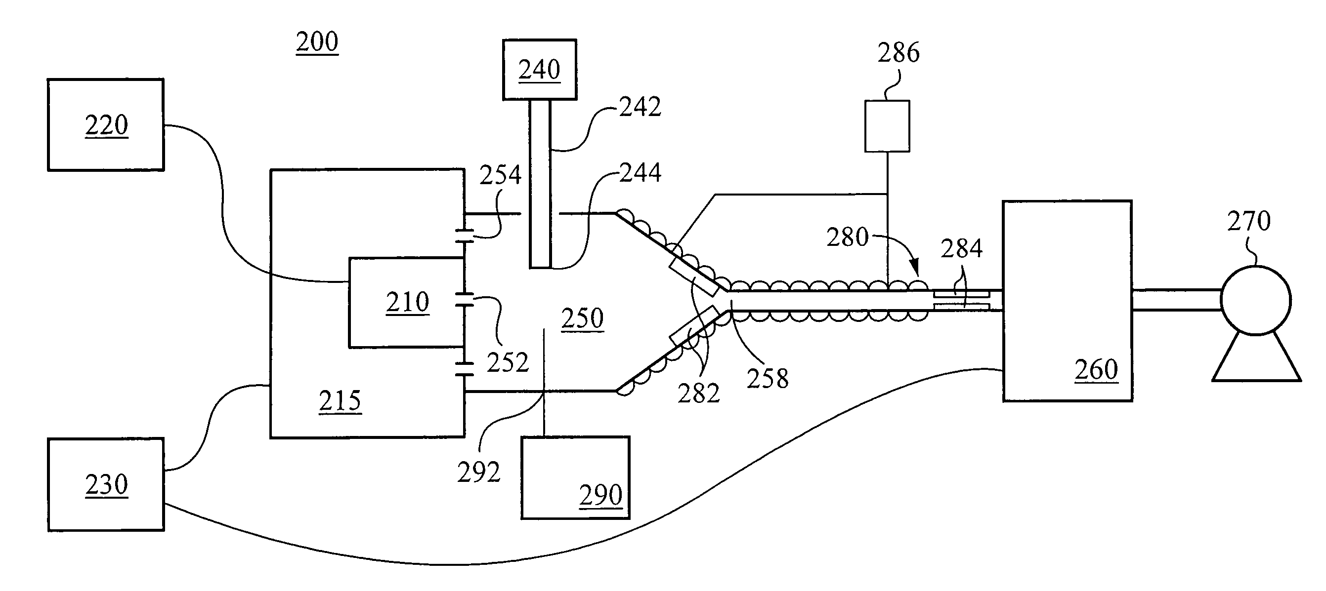
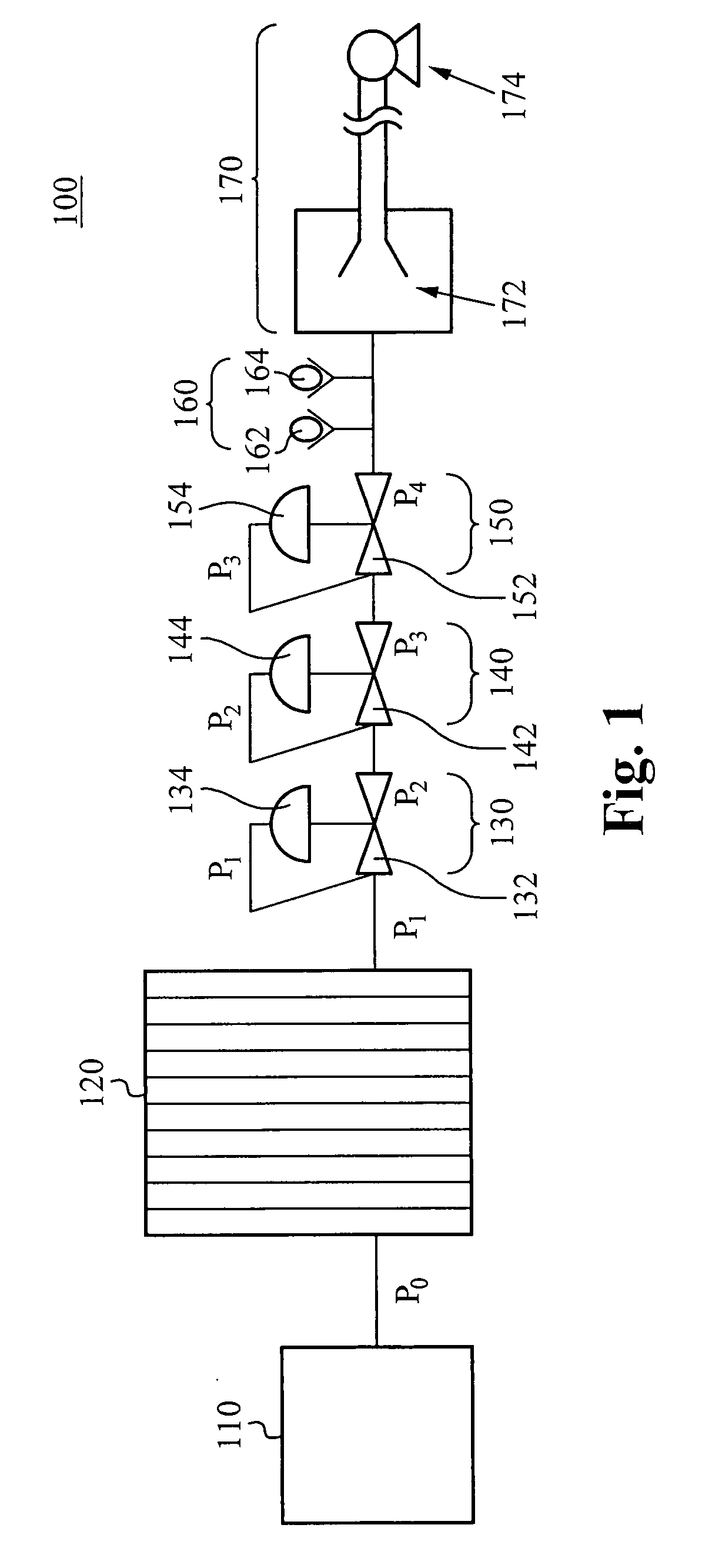
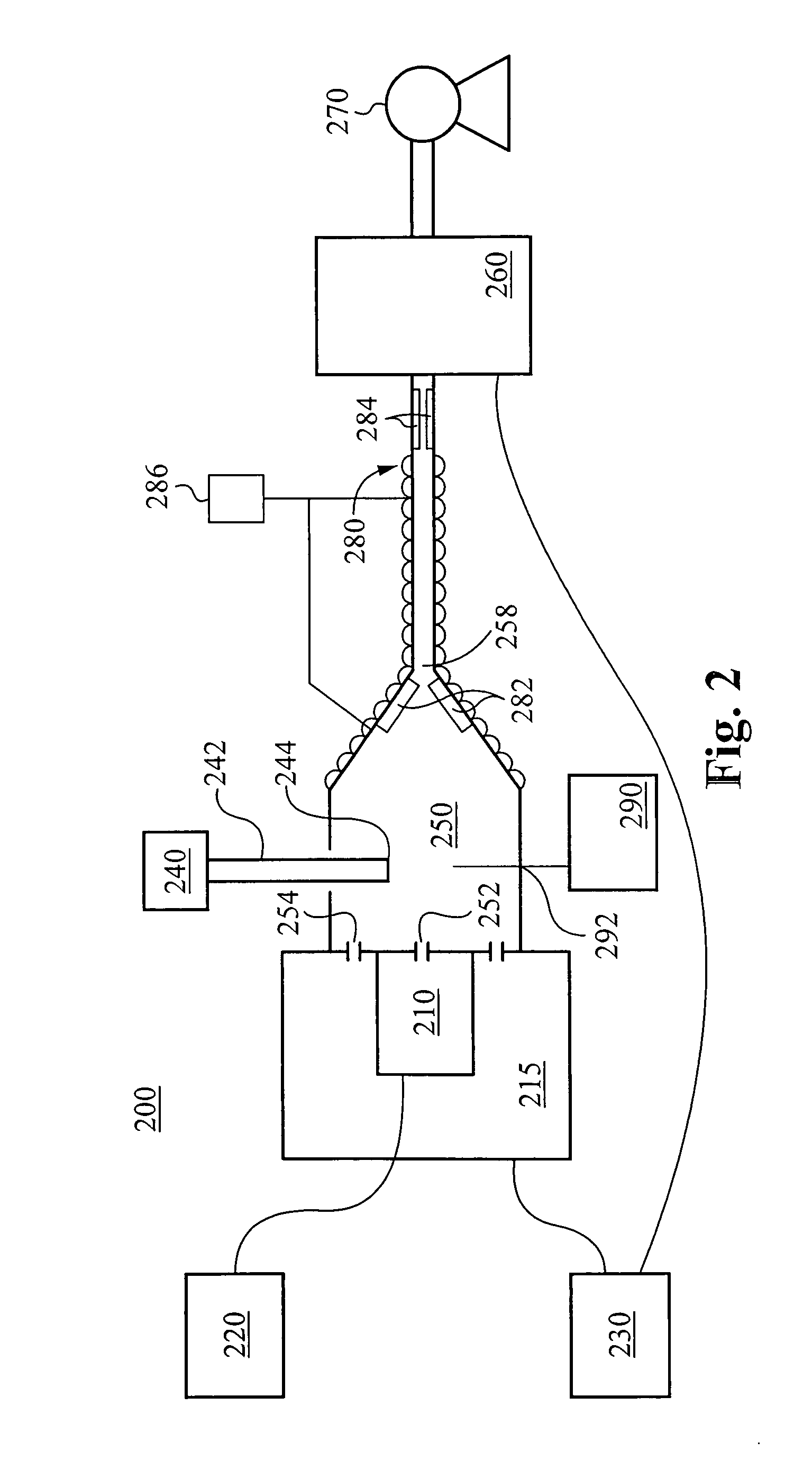
[0009]In another aspect of the present invention, a method of supplying an overpressure gas to a particle production reactor operating in an environment having an ambient pressure is provided. The reactor has a working gas inlet, a conditioning fluid inlet, a powder supply inlet, and a mixture outlet. A suction generator provides a varying suction at the mixture outlet of the particle production reactor. A pressure regulation module receives a conditioning fluid at an original pressure from a conditioning fluid supply module. The pressure regulation module reduces the pressure of the conditioning fluid from the original pressure to a selected pressure relative to the ambient pressure, wherein the pressure regulation module maintains the reduction of the conditioning fluid pressure to the same selected pressure regardless of any changes in the suction force at the mixture outlet of the reactor. A supply chamber receives the conditioning fluid at the selected pressure from the pressure regulation module, wherein the supply chamber is fluidly coupled to the conditioning fluid inlet of the particle production reactor. The particle production reactor receives a working gas through the working gas inlet. The particle production reactor energizes the working gas to form a plasma stream. The particle production reactor receives powder particles through the powder supply port. The particle production reactor receives the conditioning fluid from the supply chamber through the conditioning fluid inlet. The particle production chamber combining the plasma stream, the powder particles and the conditioning fluid, thereby altering the powder particles and forming a mixture stream. The altered powder particles are entrained within the mixture stream. The mixture stream flows to the mixture outlet of the particle production reactor.
[0013]In preferred embodiments, the pressure regulation module further comprises a pressure relief module fluidly coupled between the pressure regulator and the supply chamber. The pressure relief module receives the conditioning fluid from the pressure regulator and vents a portion of the conditioning fluid to the environment, thereby reducing the pressure of the conditioning fluid prior to entry into the supply chamber.
[0018]In some embodiments, the conditioning fluid is argon. Furthermore, the selected pressure at which the pressure regulation module provides the conditioning fluid is preferably equal to or less than 2 inches of water relative to the ambient pressure, sufficiently minimizing the pressure differential in the system, while still providing a constant overpressure regardless of any variation in suction force at the reactor outlet.

Problems solved by technology

However, when using such systems, care must be taken to produce or condition sensitive or reactive materials.
When operating in an ambient pressure environment, contamination may occur if the internal pressure of the system falls below the ambient pressure.
However, completely airtight seals, if available, are very expensive.
However, too large a differential between the system pressure and the ambient pressure can encourage leakage out of the system, which is also undesirable.
Unfortunately, in systems where the vacuum suction used is not constant, providing a fixed overpressure into the system will not effectively minimize the pressure differential between the system pressure and the ambient pressure.

Method used


Image

  • Gas delivery system with constant overpressure relative to ambient to system with varying vacuum suction
  • Gas delivery system with constant overpressure relative to ambient to system with varying vacuum suction
  • Gas delivery system with constant overpressure relative to ambient to system with varying vacuum suction

Examples


Embodiment Construction

[0025]The description below concerns several embodiments of the invention. The discussion references the illustrated preferred embodiment. However, the scope of the present invention is not limited to either the illustrated embodiment, nor is it limited to those discussed, to the contrary, the scope should be interpreted as broadly as possible based on the language of the Claims section of this document.

[0026]In the following description, numerous details and alternatives are set forth for purpose of explanation. However, one of ordinary skill in the art will realize that the invention can be practiced without the use of these specific details. In other instances, well-known structures and devices are shown in block diagram form in order not to obscure the description of the invention with unnecessary detail.

[0027]This disclosure refers to both particles and powders. These two terms are equivalent, except for the caveat that a singular “powder” refers to a collection of particles. T...


PUM

PropertyMeasurementUnit
Lengthaaaaaaaaaa
Pressureaaaaaaaaaa

Abstract

A system operating in an environment having an ambient pressure, the system comprising: a reactor configured to combine a plasma stream, powder particles and conditioning fluid to alter the powder particles and form a mixture stream; a supply chamber coupled to the reactor; a suction generator configured to generate a suction force at the outlet of the reactor; a fluid supply module configured to supply the conditioning fluid at an original pressure; and a pressure regulation module configured to: receive the conditioning fluid from the fluid supply module, reduce the pressure of the conditioning fluid from the original pressure to a selected pressure relative to the ambient pressure regardless of any changes in the suction force at the outlet of the reactor, and supply the conditioning fluid at the selected pressure to the supply chamber.

Description

CROSS-REFERENCE TO RELATED APPLICATIONS[0001]The present application claims priority to co-pending U.S. patent application Ser. No. 11 / 110,341, filed on Apr. 19, 2005, entitled, “HIGH THROUGHPUT DISCOVERY OF MATERIALS THROUGH VAPOR PHASE SYNTHESIS” and to co-pending U.S. Provisional Application Ser. No. 60 / 928,946, filed May 11, 2007, entitled “MATERIAL PRODUCTION SYSTEM AND METHOD,” both of which are hereby incorporated by reference as if set forth herein.FIELD OF THE INVENTION[0002]The present invention relates to systems for and methods of providing a constant overpressure gas to a system with varying internal pressure.BACKGROUND OF THE INVENTION[0003]Some particle production systems rely on vacuum suction forces to carry particle-containing mixtures from a reactor region to a collection region. However, when using such systems, care must be taken to produce or condition sensitive or reactive materials.[0004]When operating in an ambient pressure environment, contamination may occ...

Claims


Application Information

Patent Timeline
IPC IPC(8): B01J19/08
CPCB22F9/12Y10T156/15F28D7/024F28D7/08F28D15/00F28F27/00B22F2999/00B01J19/0013Y10S623/923B01J25/00B01J25/02Y10S623/92B22F2202/13Y10T137/0391Y10T137/2076A61L2/18B22F2203/13B01J19/088B01J37/0018B01J37/349B01J37/06B01J2219/0805B01J2219/0894B01J35/56B01J2/16B01J37/0027B01J2219/0879F28C3/16
Inventor LAYMAN, FREDRICK P.
Owner UMICORE AG & CO KG
Learn More