Coupling assembly for plumbing fitting

a technology for plumbing fittings and components, applied in the direction of couplings, water supply installation, operating means/releasing devices of valves, etc., can solve the problems of bulky spouts, prone to breakage of covers and plugs used to hide fasteners, and limited shape, size and configuration of control handles

Inactive Publication Date: 2008-11-13
KOHLER CO
View PDF14 Cites 16 Cited by
  • Summary
  • Abstract
  • Description
  • Claims
  • Application Information

AI Technical Summary

Benefits of technology

[0007]In one aspect, the present invention provides a control handle assembly devoid of any exposed or clearly visible coupling components. The invention provides a control handle assembly for a plumbing fitting including a first control member having a bore and a first ledge within the bore extending radially inward to an inner dimension, and a second control member having a mounting post with a second ledge extending radially outward to an outer dimension. A clip is captured by the first and second control members between the first and second ledges. The clip is deformable and has a radial outer dimension greater than each of the inner dimension of the first ledge and the outer dimension of the second ledge so as to rotatably couple the first and second control members.

Problems solved by technology

The control handles, however, are limited in shape, size, and configuration due to the required fastener access, and the covers and plugs used to hide the fasteners are prone to breaking during removal and reassembly.
Incorporating the diverter into the spout typically results in a bulky spout coupling having a large nut or knurled coupler and an unstable fit between the spout and the balance of the faucet.

Method used


Image

  • Coupling assembly for plumbing fitting
  • Coupling assembly for plumbing fitting
  • Coupling assembly for plumbing fitting

Examples


Embodiment Construction

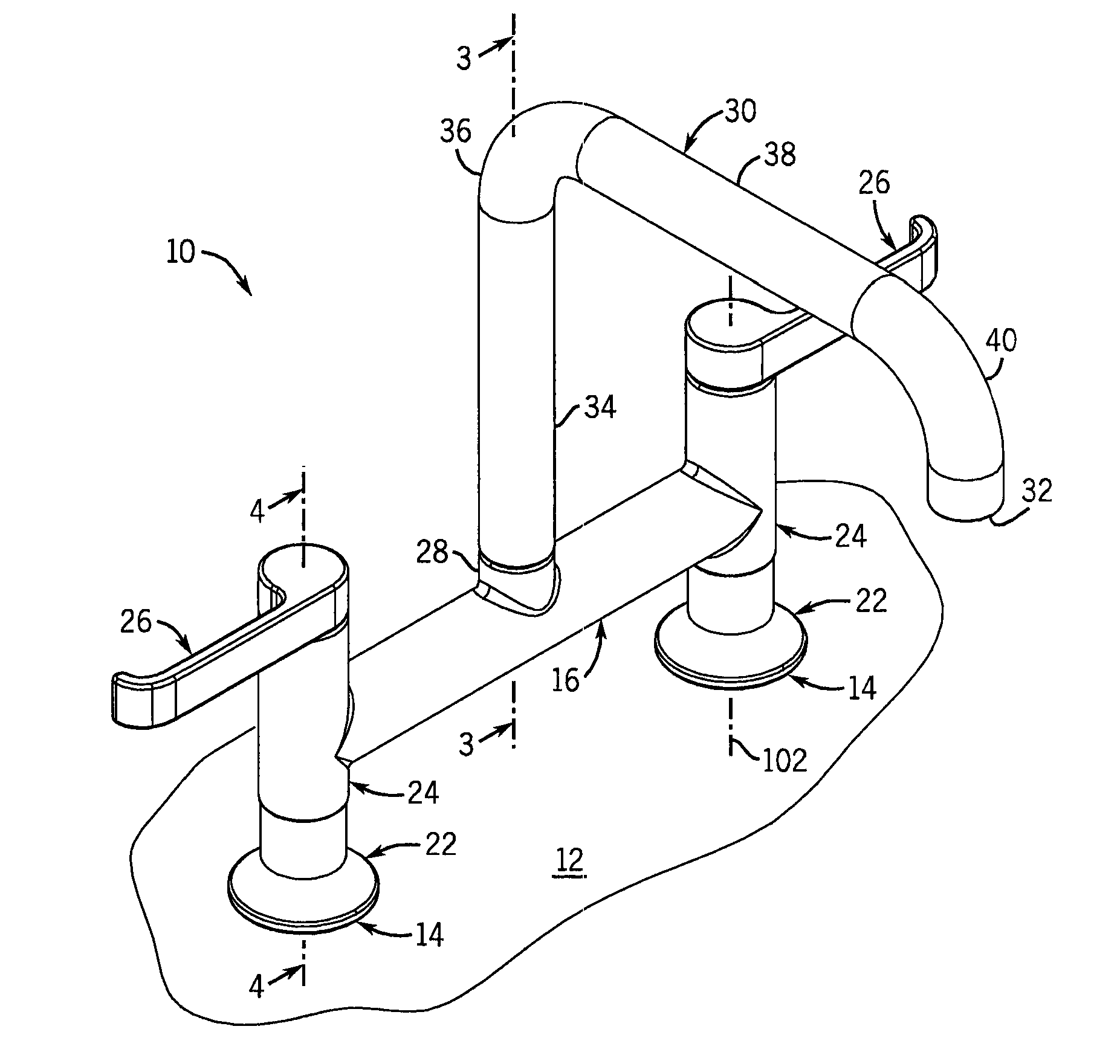
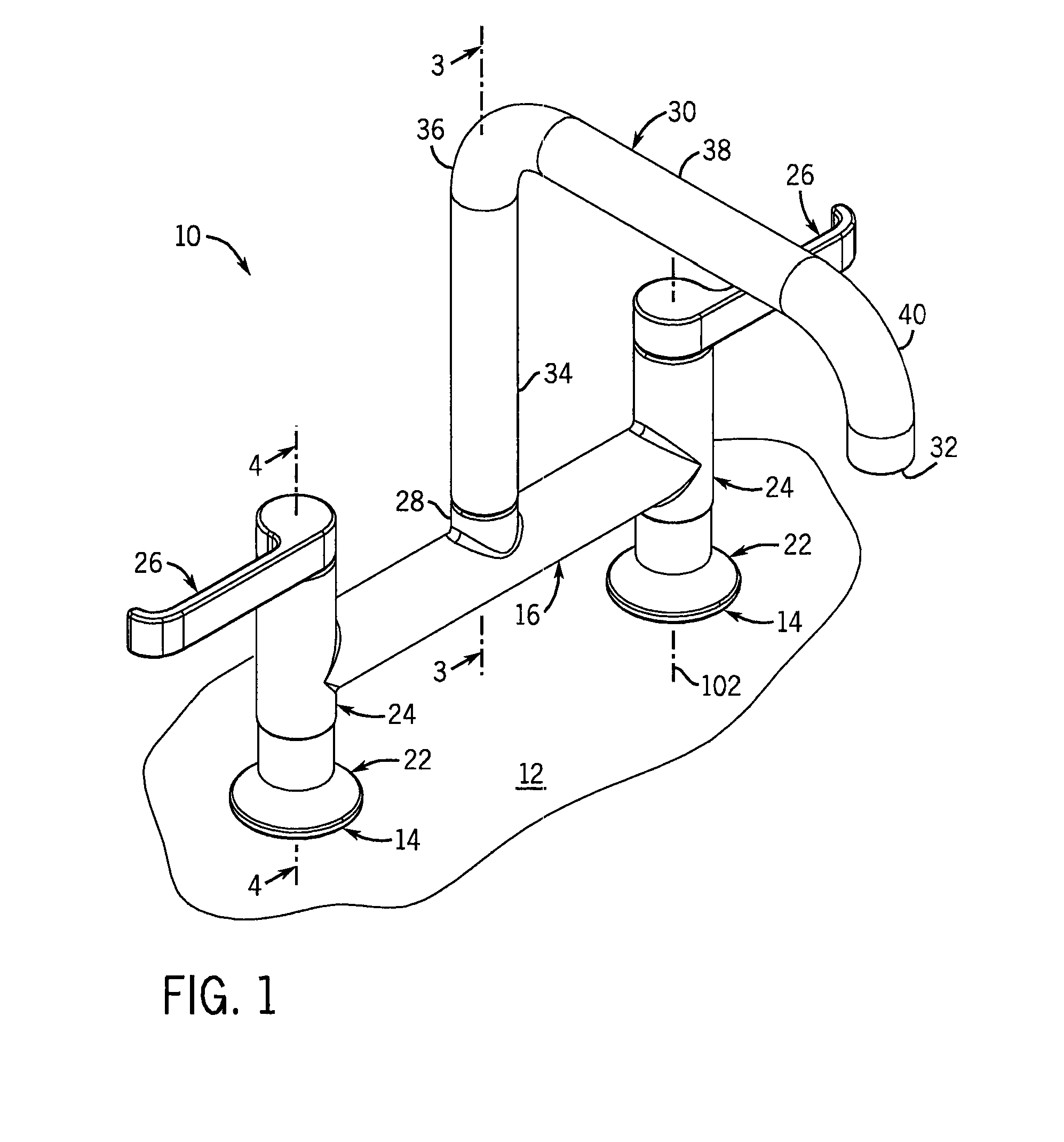
[0022]The example embodiments are described with reference to a type of faucet commonly referred to as a “bridge faucet” (i.e., a faucet including a pair of spaced apart handles connected by an intermediate bridge). While the invention is described with reference to this type faucet, the invention is equally applicable to other types of plumbing fixtures, such as, widespread and single-hole faucets, and other application settings, such as, bath tubs and shower stalls.

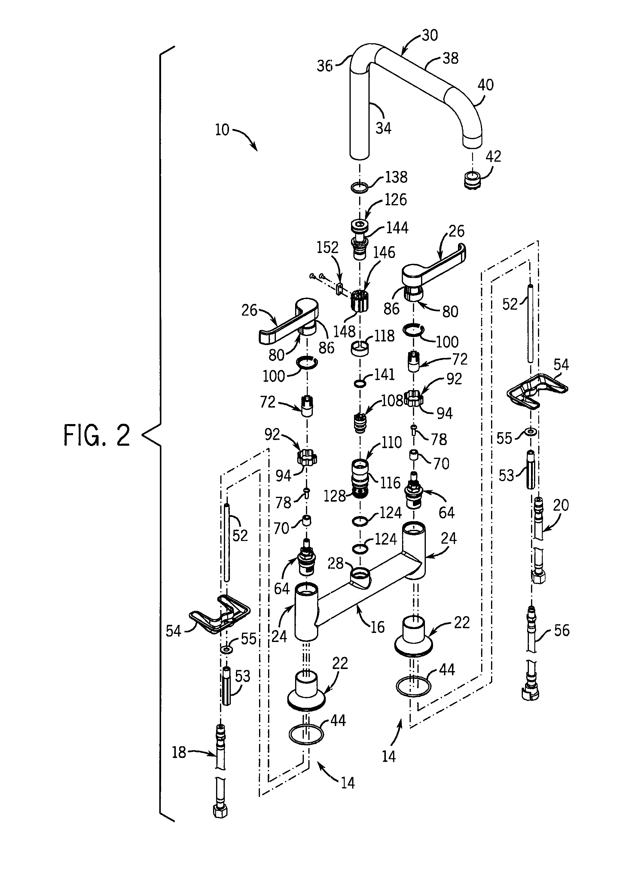
[0023]Turning first to FIG. 1, a deck mounted bridge faucet 10 is shown mounted to a substrate 12, such as a counter, tub surround, and the like. The faucet 10 includes a pair of spaced apart pillar assemblies 14 in fluid communication with a horizontal bridge 16. One of the pillar assemblies 14 is typically coupled to a hot water supply line 18 and the other to a cold water supply line 20 (shown in FIG. 2). Each pillar assembly 14 includes an escutcheon 22, a valve housing 24, and a handle 26. The bridge 16 connecting ...


PUM


Abstract

A control handle assembly for a plumbing fitting has a first control member having a bore and a ledge within the bore extending radially inward to an inner dimension, and a second control member having a mounting post with a ledge extending radially outward to an outer dimension. A deformable clip is captured by the control members between the ledges and has a radial outer dimension greater than the inner and outer dimensions of the ledges so as to rotatably couple the control members.A spout coupling assembly has a lower adaptor defining a lower passageway for housing a diverter and an upper adaptor coupled to the lower adaptor defining an upper passageway. An annular recess is formed in the upper adaptor and a collar is axially restrained in the annular recess. A spout is coupled to the collar so that the spout and collar rotate simultaneously.

Description

CROSS-REFERENCE TO RELATED APPLICATIONS[0001]This application claims priority to U.S. provisional application No. 60 / 916,736 filed May 8, 2007, which is hereby incorporated by reference as if fully set forth herein.STATEMENT OF FEDERALLY SPONSORED RESEARCH OR DEVELOPMENT[0002]Not applicable.BACKGROUND OF THE INVENTION[0003]The present invention relates to a plumbing fittings and fixtures. More particularly, it relates to coupling arrangements for plumbing products such as faucets and the like.[0004]Nearly all plumbing fixtures incorporate some type of fitting allowing a user to adjust such features as the volume of fluid flow, the fluid temperature, the particular path the fluid takes, to what outlet the fluid flows, and the like. To provide this control, a control handle is typically coupled to a valve (e.g., a mixing valve, gate valve, butterfly valve, ball valve, etc.). The control handle and valve are often coupled by a fastener, such as a set screw, extending through a portion ...

Claims


Application Information

Patent Timeline
Patent Type & Authority Applications(United States)
IPC IPC(8): F16L37/28F16K11/00
CPCE03C1/0404E03C1/0412Y10T403/7176F16K31/602Y10T74/20474F16K11/207Y10T137/6024Y10T137/86493Y10T137/87249Y10T137/87684Y10T137/9464
Inventor ESCHE, JOHN C.BARES, WILLIAM R.
Owner KOHLER CO
Why Eureka
Try Eureka