Rotary electric system designed to utilize zero-phase circuit

a technology of electric system and zero-phase circuit, which is applied in the direction of electronic commutators, motor/generator/converter stoppers, dynamo-electric converter control, etc., can solve the problems of increasing the cost of control apparatus, and achieve the effect of enhancing the effect of increasing a voltage and creating torqu

Inactive Publication Date: 2008-11-13
DENSO CORP
View PDF8 Cites 35 Cited by
  • Summary
  • Abstract
  • Description
  • Claims
  • Application Information

AI Technical Summary

Benefits of technology

[0032]In view of the background, an object of at least one aspect of the present invention is to provide a rotary electric system having star-connected multiphase windings with a neutral point with which a direct voltage power source is connected; this rotary electric system is capable of enhancing the effect of increasing a voltage to be applied to an inverter of the rotary electric system as compared with conventional rotary electric systems.
[0033]According to one aspect of the present invention, there is provided a rotary electric system. The rotary electric system includes a rotary electric machine provided with an armature core and star-connected multiphase windings with a neutral point wound in the armature core. The rotary electric machine works to create torque when the star-connected multiphase windings are energized. The rotary electric system includes a direct current power source connected with the neutral point of the star-connected multiphase windings. The rotary

Problems solved by technology

The conventional structure of the control apparatus h

Method used


Image

  • Rotary electric system designed to utilize zero-phase circuit
  • Rotary electric system designed to utilize zero-phase circuit
  • Rotary electric system designed to utilize zero-phase circuit

Examples


first embodiment

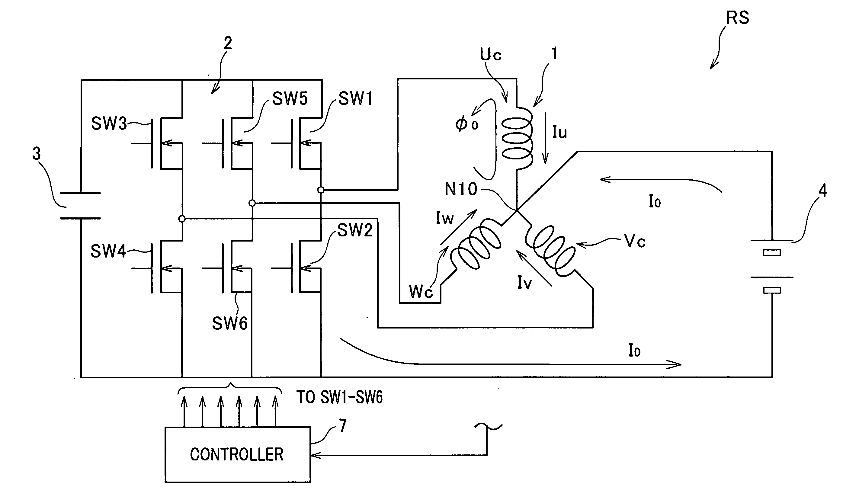
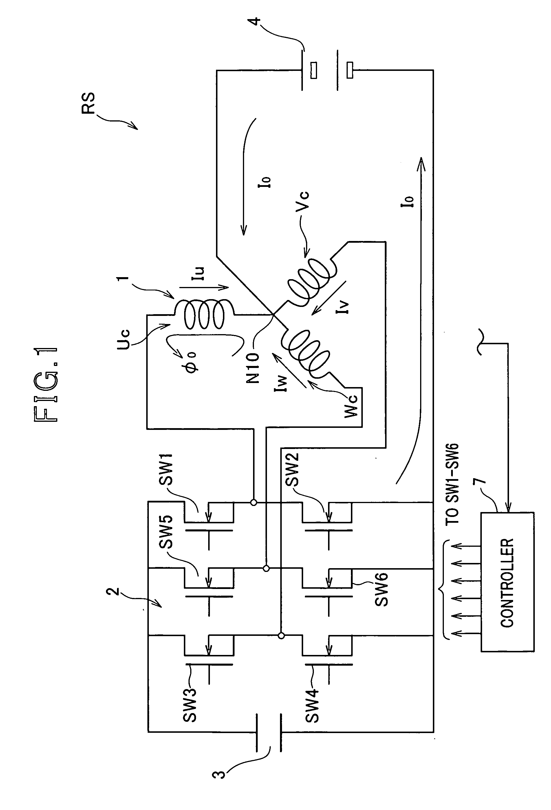
[0050]Referring to FIG. 1, there is provided a rotary electric system RS according to a first embodiment of the present invention.

[0051]The rotary electric machine RS includes a fourteen-pole, 12-slot three-phase rotary electric machine 1, a three-phase inverter 2, a capacitor 3, a battery 4 as an example of DC power supplies, and a controller 7.

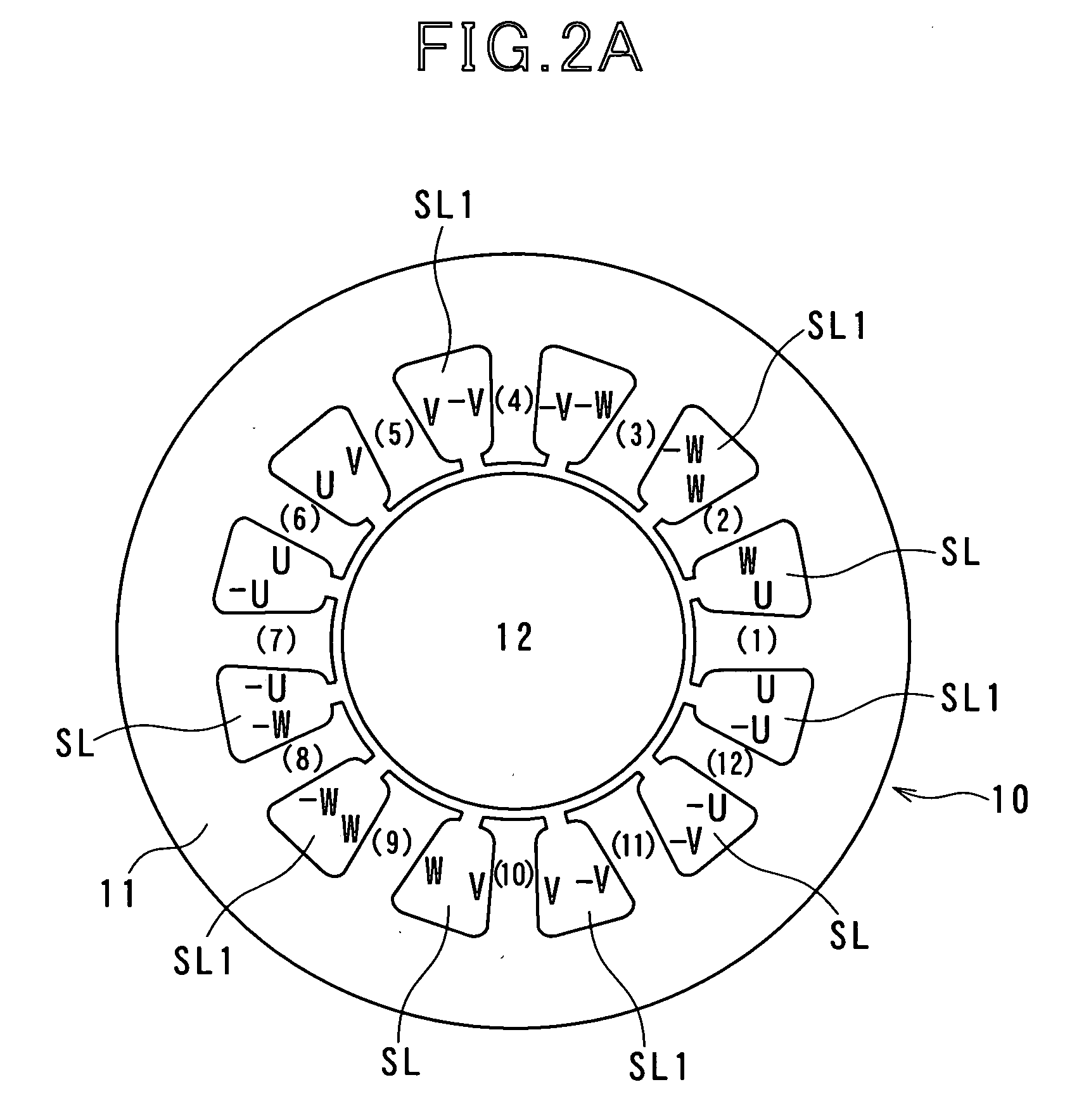
[0052]Referring to FIGS. 2A and 2B, the rotary electric machine 1 is provided with an annular rotor 12. The rotor 12 is provided at its circumferential portion with the fourteen poles consisting of alternate north poles (N) and south poles (S). The fourteen poles has a pole pitch of an electric angle of 180 degrees.

[0053]The rotary electric machine 1 includes a stator 10 serving as an armature. The armature 10 has an annular armature core 11. The armature core 11 is disposed around the outer periphery of the outer periphery of the rotor 12 such that the inner periphery of the armature core 11 is opposite to the outer periphery of the rotor 1...

second embodiment

[0106]FIG. 4 schematically illustrates a winding structure of an armature 11A and a pole structure of a rotor 12A of a ten-pole, 12-slot rotary electric system RSA according to a second embodiment of the present invention.

[0107]The structure of the rotary electric system RSA according to the second embodiment is substantially identical to that of the rotary electric system RS according to the first embodiment except for the winding structure of the rotary electric system RSA and the number of poles of a rotor 12A thereof. So, like parts between the rotary electric systems RS and RSA according to the first and second embodiments, to which like reference characters are assigned, are omitted or simplified in description.

[0108]Like the first embodiment, when reference numerals (teeth numbers) of 1 to 12 are assigned to first to twelfth teeth of an armature core 11A formed on the inner periphery thereof, the first (1) to twelfth (12) teeth are equally spaced to define first to twelfth sl...

third embodiment

[0138]FIG. 5 schematically illustrates a rotary electric system RSB according to a third embodiment of the present invention.

[0139]The structure of the rotary electric system RSB according to the third embodiment is substantially identical to that of the rotary electric system RS according to the first embodiment except for the connection between the battery 4 and each of the rotary electric machine 1 and the three-phase inverter 2. So, like parts between the rotary electric systems RS and RSB according to the first and third embodiments, to which like reference characters are assigned, are omitted or simplified in description.

[0140]In the rotary electric machine RSB, the negative electrode of the battery 4 is connected with the common neutral point N10 of the three-phase coils Uc, Vc, and Wc.

[0141]The positive electrode of the battery 4 is connected with the one end of each of the series-connected switching elements SW1 and SW2, the series-connected switching elements SW3 and SW4, ...


PUM


Abstract

In a rotary electric system, a rotary electric machine is provided with an armature core and star-connected multiphase windings with a neutral point wound in the armature core. Each of the star-connected multiphase windings has a predetermined winding configuration that prevents, when a zero-phase current is supplied from a direct current power source to the star-connected multiphase windings via the neutral point, a zero-phase magnetic flux created in the armature core based on the zero-phase current flowing in each phase winding of the star-connected multiphase windings from being cancelled out by a zero-phase magnetic flux created in the armature core based on the zero-phase current flowing in another one phase winding of the star-connected multiphase windings.

Description

CROSS REFERENCE TO RELATED APPLICATIONS[0001]This application is based on Japanese Patent Applications 2007-125823 and 2007-296653 filed on May 10, 2007 and Nov. 15, 2007, respectively. The descriptions of the patent applications are all incorporated herein by reference.FIELD OF THE INVENTION[0002]The present invention relates to a rotary electric system equipped with a rotary electric machine, and more particularly to such a rotary electric system designed to use a zero-phase circuit by connecting a direct voltage power source with a neutral point of star-connected multiphase windings thereof.BACKGROUND OF THE INVENTION[0003]An apparatus for controlling a brushless motor, as an example of rotary electric machines, is commonly designed to use a step-up converter for increasing a DC (Direct Current) voltage to be inputted to an inverter in order to increase a voltage to be applied to the brushless motor. This aims at reducing the effects of a back electromotive force generated by the...

Claims


Application Information

Patent Timeline
IPC IPC(8): H02P6/00H02K1/00
CPCB62D5/046H02J7/1492H02P23/0036H02P31/00H02P2209/01Y02T10/92H02P23/0004
Inventor TANIGUCHI, MAKOTO
Owner DENSO CORP
Why Eureka
Try Eureka