Optical cable and method of manufacturing an optical cable

Inactive Publication Date: 2008-11-13
CORNING CABLE SYST LLC
View PDF4 Cites 57 Cited by
  • Summary
  • Abstract
  • Description
  • Claims
  • Application Information

AI Technical Summary

Benefits of technology

[0008]According to another embodiment, an optical cable comprises a tight buffered optical fiber, a buffer tube surrounding the tight buffered optical fiber, a jack

Problems solved by technology

Furthermore, it is required that the cable is amenable to field connectorization an

Method used


Image

  • Optical cable and method of manufacturing an optical cable
  • Optical cable and method of manufacturing an optical cable
  • Optical cable and method of manufacturing an optical cable

Examples


Embodiment Construction

[0018]Embodiments of the present invention will now be described more fully hereinafter with reference to the accompanying drawings. The invention may, however, be embodied in many different forms and should not be construed as limited to the embodiments set forth herein; rather, these embodiments are provided so that the disclosure will fully convey the scope of the invention to those skilled in the art. The drawings are not necessarily drawn to scale but are configured to clearly illustrate the invention. The same reference signs will be used for the same or corresponding elements in different figures.

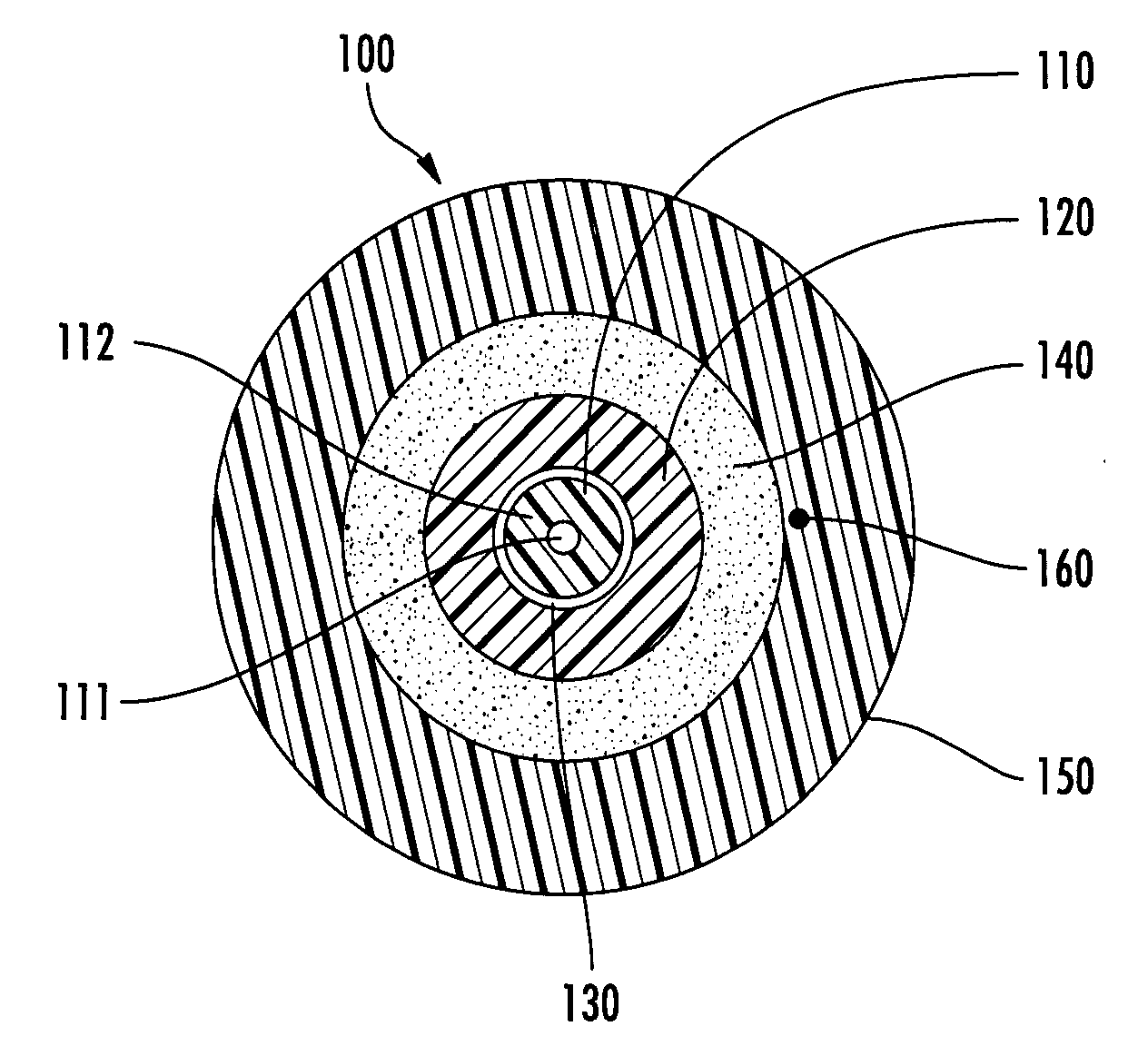
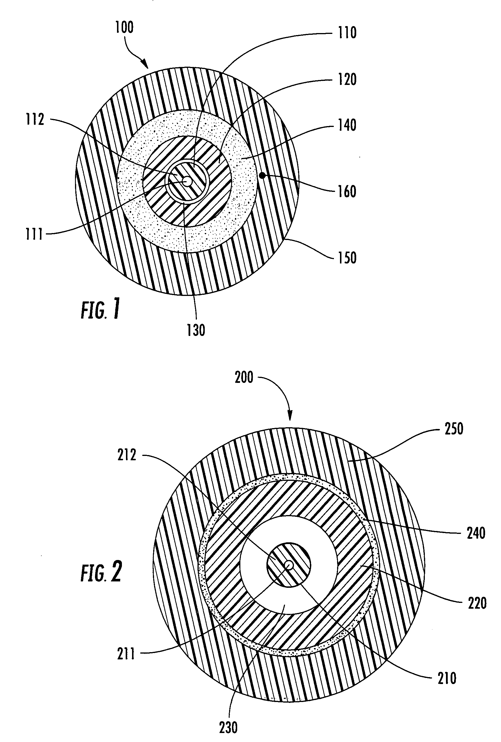
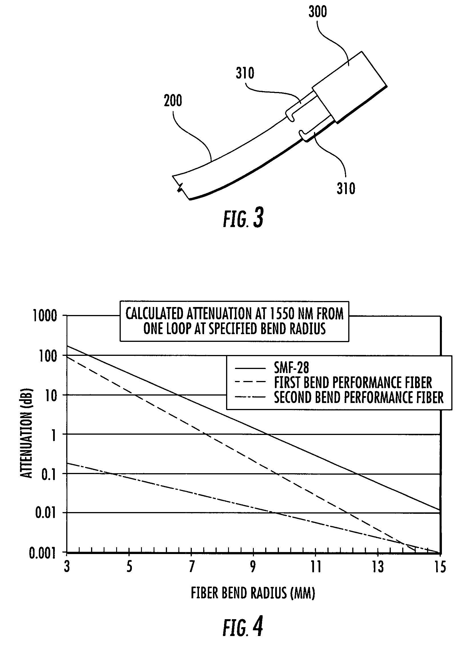
[0019]FIG. 1 illustrates a cross-sectional view of an embodiment of an optical cable 100. The optical cable comprises a buffered optical fiber 110 which may be a tight buffered optical fiber. The buffered optical fiber comprises a fiber core 111 and a buffer layer 112. The buffered optical fiber is arranged within a buffer tube 120 which surrounds the buffered optical fiber 110. A ga...


PUM


Abstract

An optical cable comprises a buffered optical fiber which is arranged within a buffer tube. The buffer tube is extruded around the buffered optical fiber such that a small gap, preferably in a range between about 40 μm and about 100 μm, is formed between the buffered optical fiber and the buffer tube. A layer of strength member elements is disposed around the buffer tube. A cable jacket is extruded around the strength member elements wherein the strength member elements are bonded to the cable jacket.

Description

FIELD OF THE INVENTION [0001]The present invention relates to an optical cable to be used for indoor and / or outdoor applications and to a method for producing an optical cable to be used for indoor and / or outdoor applications.BACKGROUND OF INVENTION [0002]In the wiring of premises with fiber optic cables, so-called drop cables are used for routing optical fibers to houses, apartments and multi-dwelling units. A drop cable may be adapted for being laid in outdoor as well as indoor areas. In the outdoor area a drop cable may be used as an aerial cable suited for a short span length. A drop cable may also be laid in the soil for making optical connections from a service provider's demarcation point to the end user.[0003]A drop cable should fulfill certain requirements. The cable should be small enough to route easily through the premises, but large enough to be easy to handle. During the installation the cable often has to be bent around corners outside or inside of the premises. Hence...

Claims


Application Information

Patent Timeline
IPC IPC(8): G02B6/44
CPCG02B6/4402G02B6/4433
Inventor KUNDIS, DIETERMERBACH, GERHARDHURLEY, WILLIAM C.WUNSCH, GUNTER
Owner CORNING CABLE SYST LLC
Why Eureka
Try Eureka