This helps you quickly interpret patents by identifying the three key elements:
Problems solved by technology
Method used
Benefits of technology
Benefits of technology
[0012]In consideration of the above circumstances, an object of the present invention is to provide a centrifugal blower with reduced noise.
[0043]According to the centrifugal blower according to the present invention, since backflow is prevented, noise is significantly reduced compared to the conventional centrifugal blower and it is unlikely to cause discomfort to a user, while operation can be carried out stably to perform excellent blowing.
Problems solved by technology
Since this backflow interferes with the flow of the air that has been taken into the casing from the bell-mouth (hereinafter, this flow is referred to as the “main flow”), noise is generated and operation of the centrifugal blower becomes unstable.
However, even by employing such a configuration a significant backflow prevention effect could not be obtained.
When operating a blower in such an area, the impeller stalls, airflow within the casing becomes unstable, and noise level increases.
Method used
Image
Click on the blue label to locate the original text in one second.
Reading with bidirectional positioning of images and text.
Examples
first embodiment
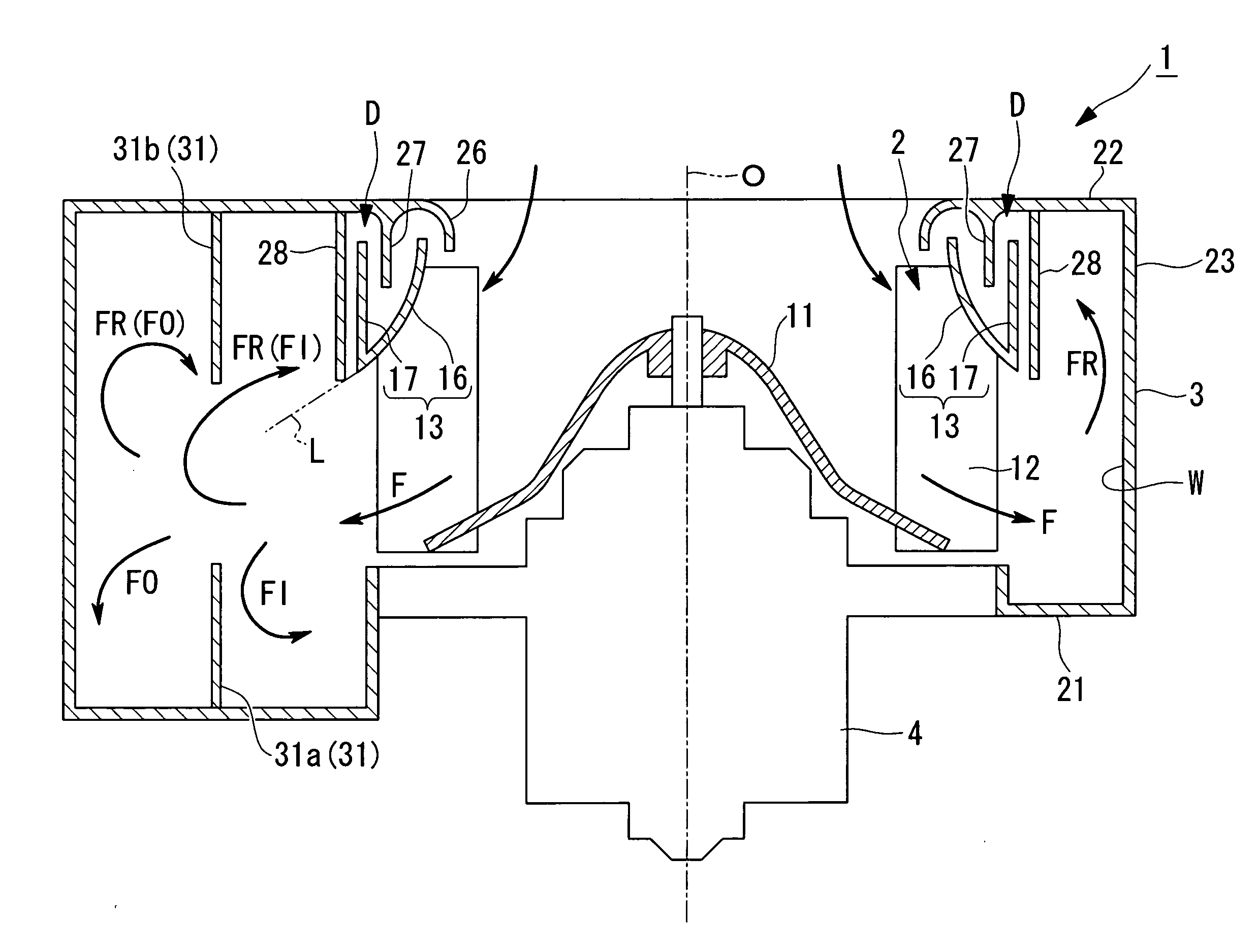
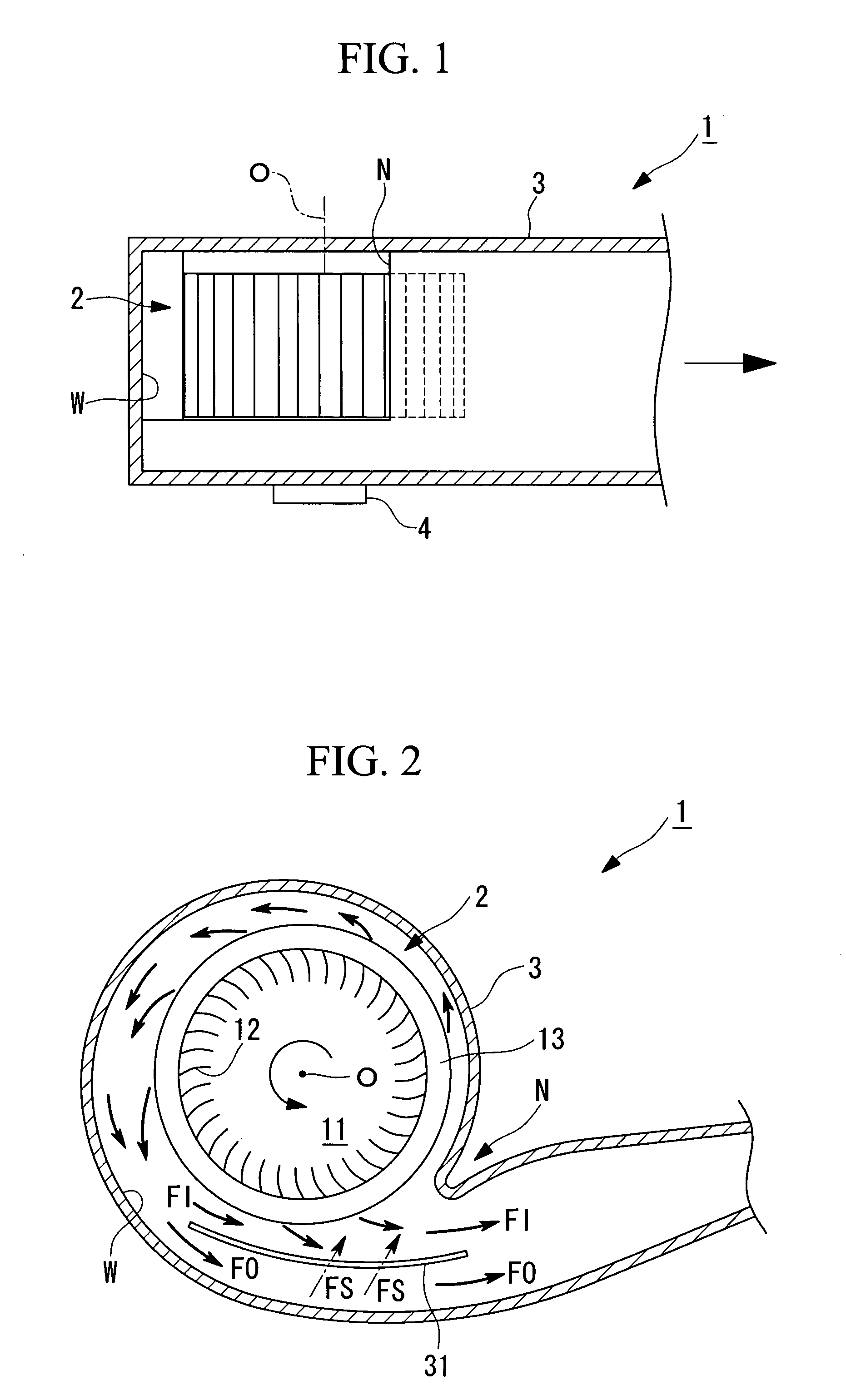
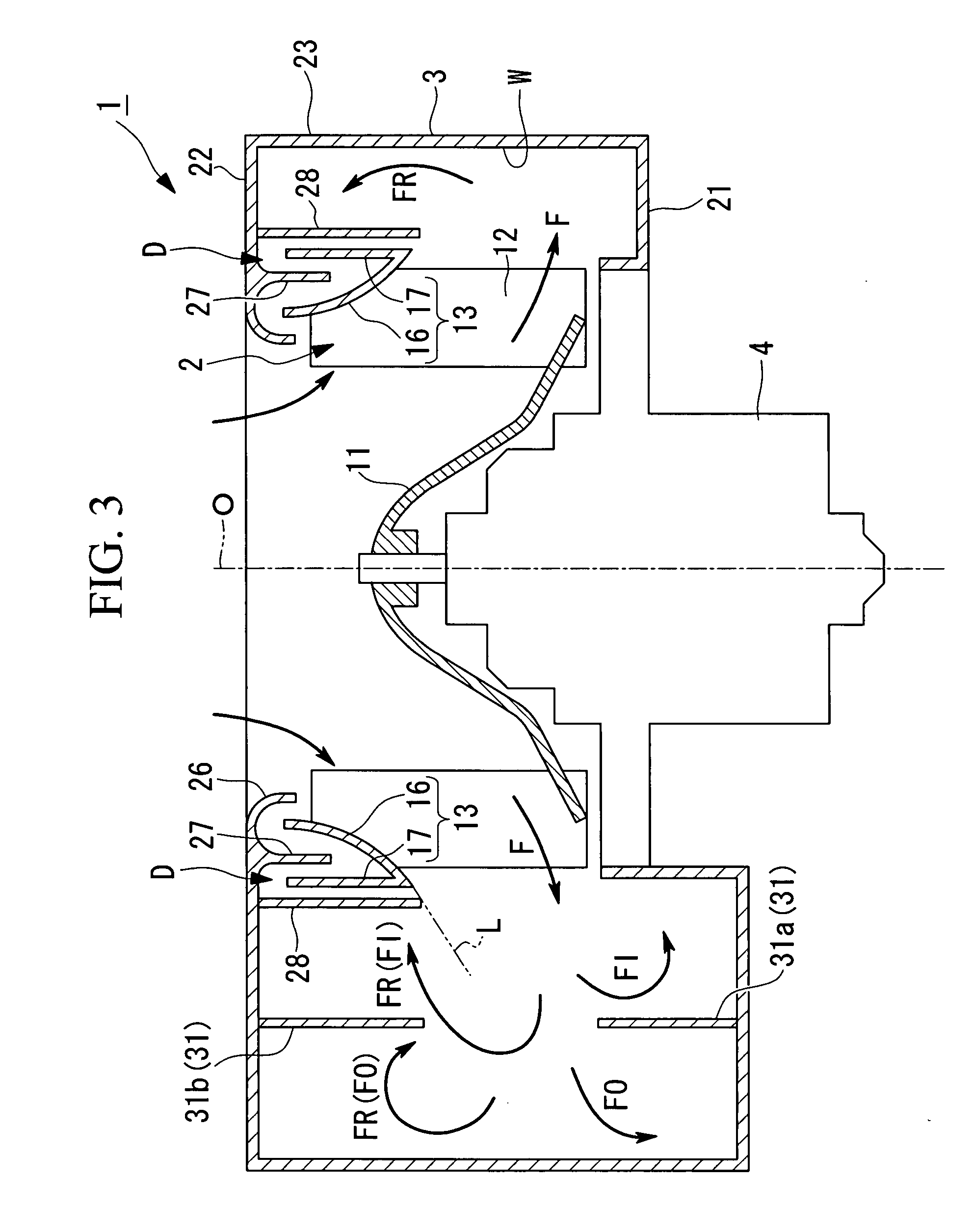
[0054]A first embodiment of the present invention is described below, with reference to FIG. 1 through FIG. 3.
[0055]A centrifugal blower 1 according to the present embodiment is used as a blower of a vehicle air conditioner.
[0056]This centrifugal blower 1 has an impeller 2, a casing 3 that houses the impeller 2 and forms a spiral flow passage W surrounding the radial direction outside of the impeller 2, and a driving device 4 that rotates the impeller 2 about an axis O.
[0057]Here, although not shown in the drawing, provided on a downstream side of the spiral flow passage W of the centrifugal blower 1, are each of the flow passages (face side flow passage, foot side flow passage, defrost side flow passage, and so forth) of, a vehicle air conditioner and a device (heat exchanger for cooling, heater core, and so forth) that conditions the air that has been fed into the spiral flow passage W. At an entry of each of the flow passages there is provided a damper, the opening and closing of...
second embodiment
[0084]A second embodiment of the present invention is described below, with reference to FIG. 6 through FIG. 8.
[0085]A centrifugal blower 51 according to the present embodiment is characterized mainly in that in the centrifugal blower 1 described in the first embodiment, the casing 3 has a wind shielding plate 52 that rises from the area in the vicinity of a start point S of the spiral flow passage W of the bell-mouth 26 toward the outside of the casing 3.
[0086]Hereinafter, structures similar to or the same as those in the centrifugal blower 1 described in the first embodiment are denoted by the same reference symbols, and their detailed description is omitted.
[0087]As shown in FIG. 6, FIG. 7 (a) and FIG. 7 (b), the wind shielding plate 52 is provided so as to overhang above the casing 3 along the inner periphery of the bell-mouth 26, and is formed in a curved surface having a convex shape toward the radial direction outside.
[0088]Moreover, as shown in FIG. 7 (a), the wind shielding...
third embodiment
[0092]A third embodiment of the present invention is described below, with reference to FIG. 9.
[0093]A centrifugal blower 61 of the present embodiment uses a casing 63 in the centrifugal blower 1 shown in the first embodiment instead of the casing 3, and it uses a shroud 73 instead of the shroud 13. Hereinafter, structures similar to or the same as those in the centrifugal blower 1 described in the first embodiment are denoted by the same reference symbols, and their detailed description is omitted.
[0094]The casing 63, is the casing 3 with the backflow suppressing wall 28 removed.
[0095]Moreover, in the casing 63, the casing side barrier 27 is provided so as to oppose a plane that faces the radial direction outside of the shroud 73. In the present embodiment, in the top plate section 22 of the casing 63, an area that opposes a plane that faces the radial direction outside of the shroud 73 is inflected along the plane that faces the radial direction outside of the shroud 73, and this ...
PUM
Abstract
An object is to provide a centrifugal blower with reduced noise. The centrifugal blower is provided with: an impeller; a casing that houses the impeller and forms a spiral flow passage that surrounds a radial direction outside of the impeller; and a driving device that rotates the impeller about an axis. The impeller has: a bottom plate; a plurality of blades provided on a same circumference of the bottom plate; and a substantially annular plate shape shroud that has the blades interposed between it and the bottom plate, and that is disposed concentric with the bottom plate, and that connects end sections of the respective blades. The shroud has: an inclined section that comes closer to the bottom plate moving from a radial direction inside to a radial direction outside; and a shroud side barrier that rises from a position on the radial direction outside of the inclined section towards a side opposite to the bottom plate. The casing is provided with a bell-mouth that opens from a radial direction inside of the shroud to a radial direction outside, and a casing side barrier that projects to an area between the inner periphery of the shroud and the shroud side barrier.
Description
TECHNICAL FIELD[0001]The present invention relates to a centrifugal blower.BACKGROUND ART[0002]A centrifugal blower has an impeller, a casing that houses this impeller and forms a spiral flow passage around the radial direction outside of the impeller, and a driving device that rotates the impeller about the axis thereof. In the centrifugal blower the impeller is rotated by the driving device to impart a centrifugal force to the gas that has been taken into the casing and force feeding it into the flow passage. Air is supplied from the impeller to the spiral flow passage sequentially from a start point to a downstream side. Therefore, the internal pressure at the start point of the spiral flow passage is lowest and the internal pressure becomes higher close to the downstream side. The portion of the spiral flow passage one circle from the start point is adjacent to the start point, where the internal pressure is lowest. As a result, the internal pressure of the spiral flow passage i...
Claims
Application Information
Patent Timeline
Application Date:The date an application was filed.
Publication Date:The date a patent or application was officially published.
First Publication Date:The earliest publication date of a patent with the same application number.
Issue Date:Publication date of the patent grant document.
PCT Entry Date:The Entry date of PCT National Phase.
Estimated Expiry Date:The statutory expiry date of a patent right according to the Patent Law, and it is the longest term of protection that the patent right can achieve without the termination of the patent right due to other reasons(Term extension factor has been taken into account ).
Invalid Date:Actual expiry date is based on effective date or publication date of legal transaction data of invalid patent.

