Aneurysm Occlusion Devices

Inactive Publication Date: 2008-11-13
BIOMERIX CORP
View PDF99 Cites 341 Cited by
  • Summary
  • Abstract
  • Description
  • Claims
  • Application Information

AI Technical Summary

Benefits of technology

[0047]The use of a reticulated matrix which is permeable to blood or other bodily fluids allows cells or other biological tissues to access the interior surfaces of the implant. The presence of inter-connected and inter-communicating reticulated open pores, voids, channels, and/or concavities in the matrix thus permits the formation of fluid passageways or fluid access into and out of the implant.
[0048]Accordingly, an embodiment of the present invention permits total reconstruction of the parental artery by delivering a patch of the physiologically-compatible matrix across the neck of the aneurysm, thereby providing a tissue scaffold to promote e

Problems solved by technology

For example, loss of a liquid embolic agent during aneurysm filling in the absence of a seal can present a high-risk condition for the patient.
Sim

Method used


Image

  • Aneurysm Occlusion Devices
  • Aneurysm Occlusion Devices
  • Aneurysm Occlusion Devices

Examples


first embodiment

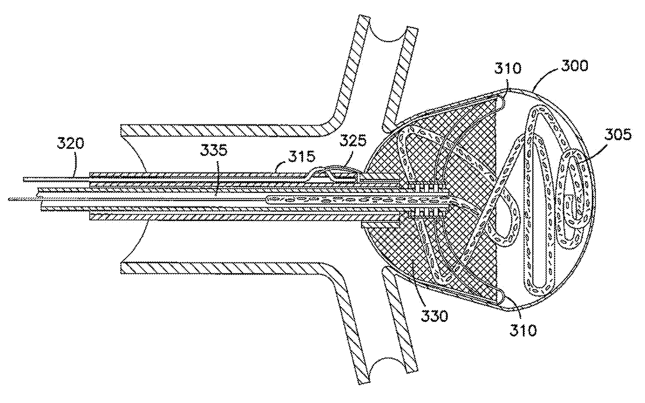
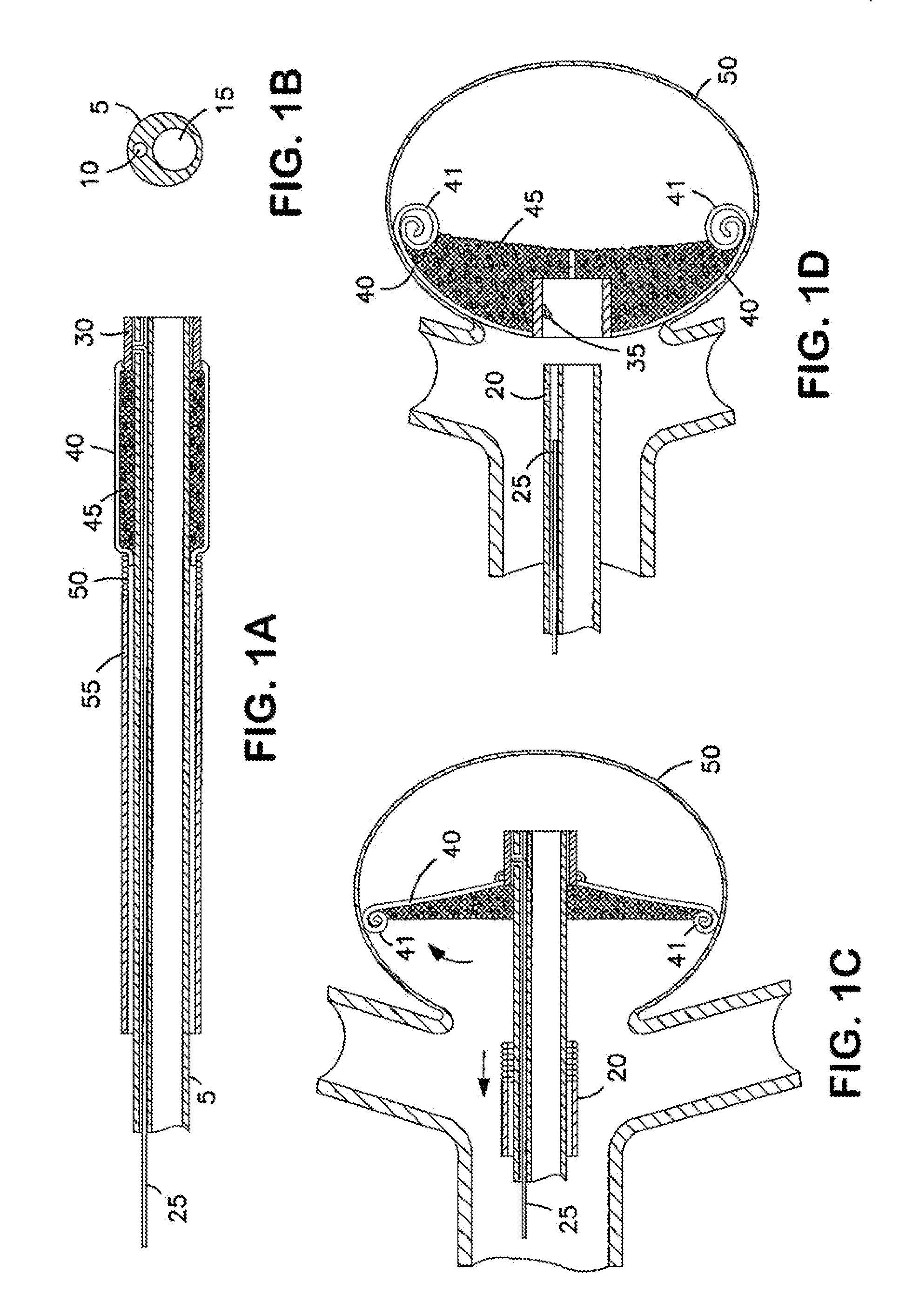
[0168]FIG. 1A illustrates an implantable device according to the invention and shows an implantable device in the collapsed state and positioned over a delivery catheter. FIGS. 1C and 1D, respectively, show the device in partially expanded and fully expanded positions in an aneurysm. FIG. 1B shows a cross-section of a delivery catheter for use with the invention. The implantable device provides an expandable three-dimensional micro-structure implant positioned to seal the neck of an aneurysm.

[0169]As shown in FIG. 1A, prior to delivery to an aneurysm 50, the foldable frame arms 40 are collapsed into a low-profile by having all the arms 40 secured or inserted in the tip coil 50 of sheath 55. The frame arms 40 support a matrix 45 sutured to them. In this collapsed delivery position, the device can be navigated through a vasculature vessel into an aneurysm. In this embodiment of the invention, the implant device has a distal center ring or hub 30 which is positioned at the tip of the d...

second embodiment

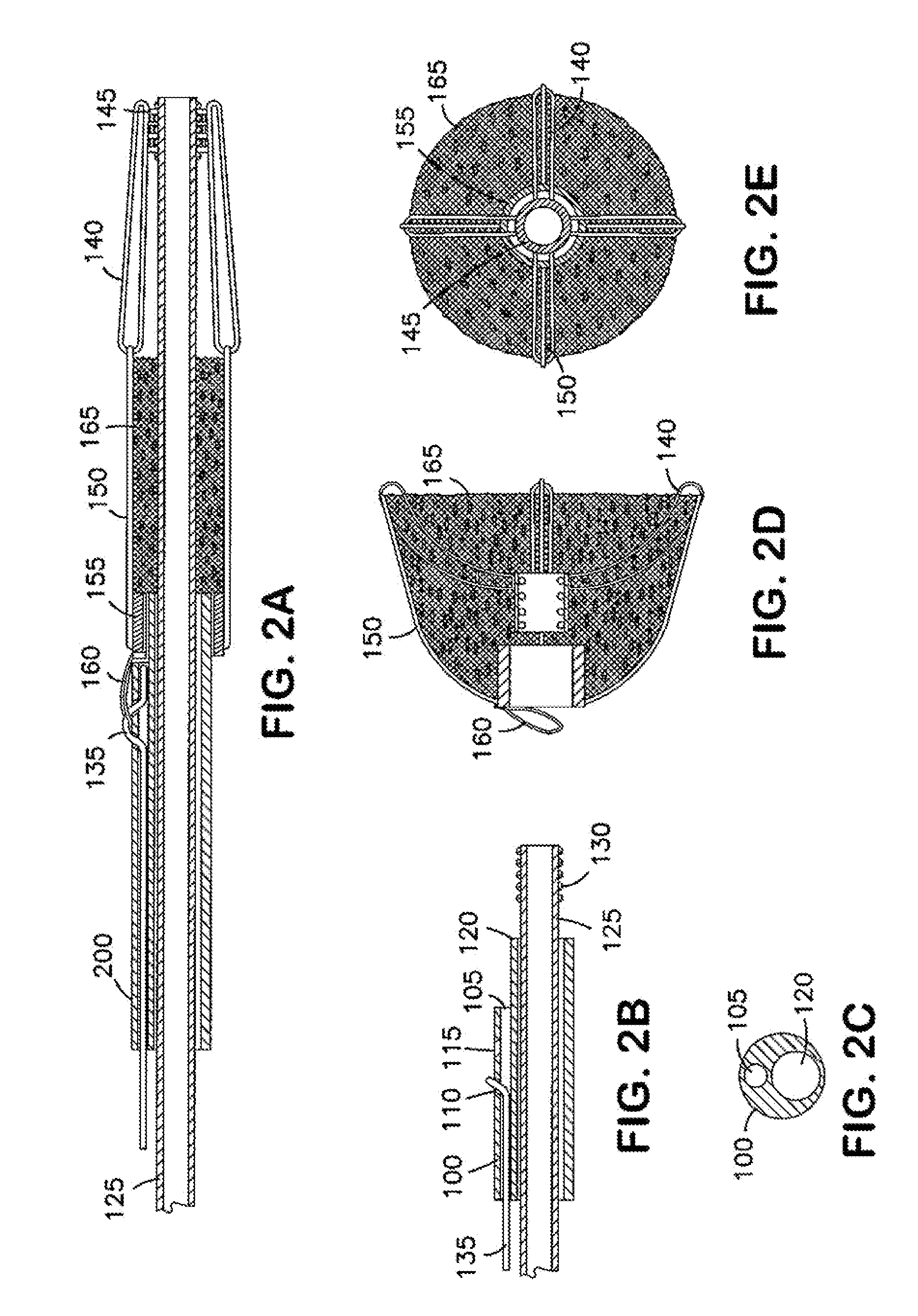
[0176]FIG. 2A illustrates the invention showing an implantable device in the collapsed state. FIGS. 2D and 2E show views of the device in an expanded position. FIGS. 2B and 2C show views of a section of a delivery catheter used with the invention.

[0177]The embodiment of the invention illustrated in FIGS. 2A-2E contains four frame arms, each in the shape of a loop. The frame arms include a proximal section 150 and a distal section 140. Each frame arm is 90° apart. In different embodiments, there may be more or fewer frame arms which may or may not be equidistantly spaced apart. Each frame arm may also expand to a greater or lesser extent than other frame arms. A matrix 165 is affixed to the frame arms. The proximal section 150 of each frame arm is affixed to a central micro-ring 155, and the distal section 140 of each frame arm is affixed to another central micro-ring 145. The center micro-ring 145 of the implant has an internal thread-coil which engages with the tip-coil screw 130 o...


PUM


Abstract

An implantable occlusion device for bridging the neck of an aneurysm comprises a biocompatible matrix. The device is movable between a compressed position prior to implantation and a generally concave or cup-shaped position following implantation. The device may comprise a frame having a plurality of elements. The frame elements have a first pre-deployment position generally parallel to a major axis of the delivery lumen, and a second post-deployment position spread radially from the major axis of the delivery lumen. The biocompatible matrix and/or the frame elements may also form or be manipulated to form a generally concave or cupped shape. The matrix can be porous or semiporous, such as a foam or a reticulated matrix. The occlusion device can be folded, twisted and/or stretched to adopt a narrow profile for loading into a coaxial delivery device and expand in place as it adopts its original shape on release. The device may be released or manipulated to a desired shape to occlude an aneurysm. Methods of using the implantable device are also provided.

Description

[0001]This applications claims priority benefit under 35 U.S.C. § 119(e) of U.S. Provisional Patent Application 60 / 869,855, filed on Dec. 13, 2007, entitled “Invertable Expandable Device for Aneurysm Occlusion Devices,” which is incorporated herein by reference in its entirety.[0002]The present invention is directed to the field of medical devices. Specifically, the present invention is directed to implantable occlusion devices for bridging the neck of an aneurysm or other vasculature in a patient, and methods for their use.BACKGROUND[0003]Current methods of treating aneurysms are designed to fill the aneurysm lumen or sac by introducing medical devices, such as coils. These methods often require deployment of multiple coils to seal the aneurysm. Many of these devices suffer from the problems associated with device compaction, such as recanalization of the aneurysm.[0004]There is an ongoing need for an improved method of treatment of an aneurysm that provides a seal of the neck of t...

Claims


Application Information

Patent Timeline
IPC IPC(8): A61M29/02
CPCA61B17/0057A61B17/12022A61B17/12113A61B17/12145A61B17/12172A61B17/12181A61B2017/00575A61B2017/00592A61B2017/00606A61B2017/00615A61B2017/00619A61M2025/0042A61B2017/12054A61B2017/12095
Inventor SEPETKA, IVANMIRIGIAN, GREGDATTA, ARINDAMHOCHBERG, STEVENABOYTES, RICARDONGO, TRANG
Owner BIOMERIX CORP
Why Eureka
Try Eureka