Robot with linearly movable support member attaching to gripper

Active Publication Date: 2008-11-20
DENSO WAVE INC
View PDF5 Cites 29 Cited by
  • Summary
  • Abstract
  • Description
  • Claims
  • Application Information

AI Technical Summary

Benefits of technology

[0008]In the SCARA robot using the bail-screw spline shaft for vertically moving the gripper, the ball-screw nut is required to be rotatably supported to the arm member in or

Problems solved by technology

This may increase the length of the bail-screw nut to be supported to the arm member.
This may lim

Method used


Image

  • Robot with linearly movable support member attaching to gripper
  • Robot with linearly movable support member attaching to gripper
  • Robot with linearly movable support member attaching to gripper

Examples


Example

First Embodiment

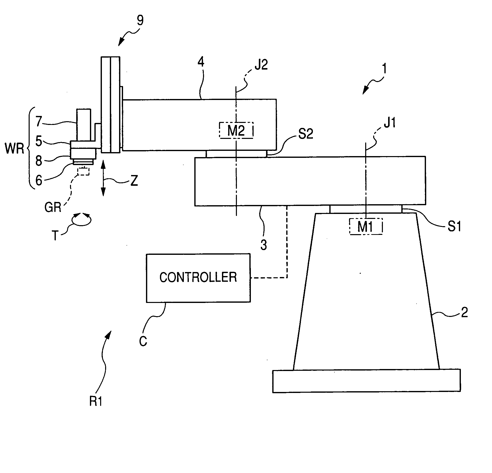
[0029]Referring to FIG. 1, there is illustrated an example of the overall structure of a SCARA robot R1 with four axes of movement according to the first embodiment of the present invention.

[0030]The SCARA robot R1 is equipped with a robot body 1 and a controller C for controlling action of the robot body 1.

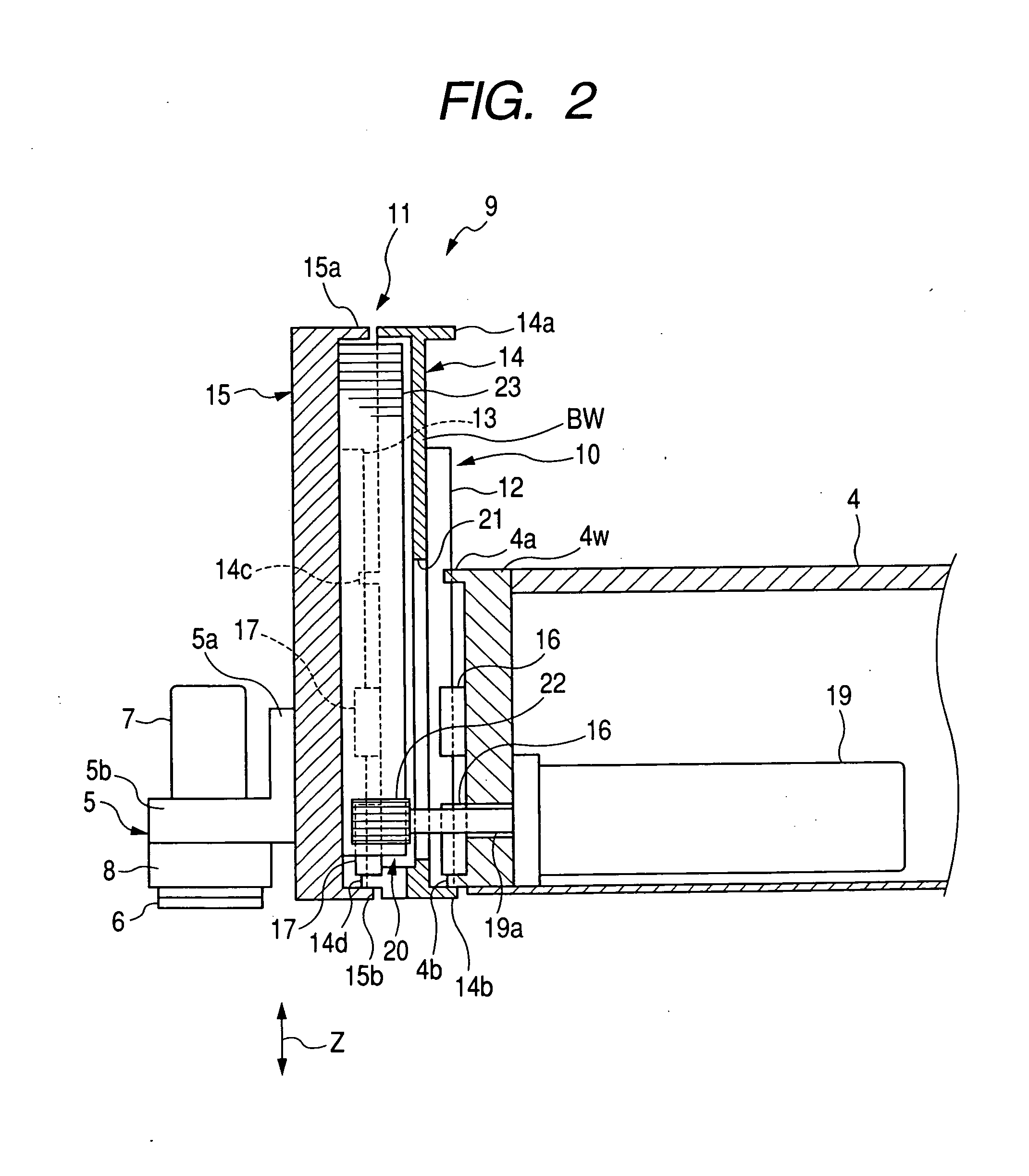
[0031]The robot body 1 consists of a base 2 mounted on an installation surface, such as a flooring of a factory. The robot body 1 also consists of a shoulder joint S1, a first arm 3, an elbow joint S2, a second arm 4, a linearly movable support member 9, an elevating member 5, and a wrist unit WR.

[0032]The base 2 has a substantial truncated pyramid or circular truncated cone.

[0033]The shoulder joint S1 has a substantially cylindrical shape and is mounted in a top portion of the base 2 such that a center axis J1 of the shoulder joint S1 is parallel to a vertical axis of the base 2 substantial orthogonal to the installation surface.

[0034]The first arm 3 has one end ...

Example

Second Embodiment

[0111]A robot according to the second embodiment of the present invention will be described hereinafter. The robot of the second embodiment has substantially the same structure as that of the robot R1 of the first embodiment except for some differences described hereinafter. For this reason, like reference characters are assigned to like parts in the robots according to the first and second embodiments so that descriptions of the parts of the robot of the second embodiment will be omitted or simplified.

[0112]FIG. 6A very schematically illustrates a robot body 1A of the robot according to the second embodiment.

[0113]The robot body 1A is designed such that, when the support member 9 is lowered from its original position, the operating rate of the first platy movable member 14 is substantially the same as that of the second platy movable member 15.

[0114]Specifically, the robot body 1A is provided with a compression coil spring 24 as an example of biasing members. The c...

Example

Third Embodiment

[0120]A robot according to the third embodiment of the present invention will be described hereinafter. The robot of the third embodiment has substantially the same structure as that of the robot R1 of the first embodiment except for some differences described hereinafter. For this reason, like reference characters are assigned to like parts in the robots according to the first and third embodiments so that descriptions of the parts of the robot of the third embodiment will be omitted or simplified.

[0121]FIG. 7 schematically illustrates a support member 9A of the robot according to the third embodiment.

[0122]The support member 9A is designed by a single support mechanism 27.

[0123]The single support mechanism 27 is made up of a platy movable member 28 formed with a pair of rail members 29, and two pairs of liner guides 30.

[0124]Each of the liner guides 30 has substantially the same structure as that of the first linear guides 16.

[0125]Blocks 30b of one pair of the lin...


PUM


Abstract

In a robot, a support member is supported to an arm to be reciprocable with respect to one of first and second sides of the arm in a predetermined direction. A rotary member of a converter is coupled to a motor, and a liner movable member of the converter is contacted to the rotary member and lined to the support member. The converter works to transfer rotary motion received y the rotary member from the motor as linear motion to the liner movable member rough a transfer contact portion between the rotary member and the liner movable member to thereby move the liner movable member together with the support member in the predetermined direction. The transfer contact portion between the rotary member and the liner movable member is located offset to the one of the fast and second sides of the arm relative to the other thereof.

Description

CROSS REFERENCE TO RELATED APPLICATIONS[0001]This application is based on Japanese Patent Applications 2007-131596 and 2008-002245 filed on May 17, 2007 and Jan. 9, 2008, respectively. This application claims the benefit of priority from the Japanese Patent Applications, so that the descriptions of which are all incorporated herein by reference.FIELD OF THE INVENTION[0002]The present invention relates to robots with a linearly movable support member attaching to a gripper for gripping workpieces.BACKGROUND OF THE INVENTION[0003]SCARA (Selective Compliance Assembly Robot Arm) robots, in other words, horizontal multi-joint robots, consist of, for instance, a base, an arm member, and a movable shaft. The arm member has one proximal end supported to the base mounted on an installation surface, such as a flooring of a factory. The movable shaft is supported to the other end of the arm member to be vertically movable and rotatable about a center axis thereof such that a higher end of the ...

Claims


Application Information

Patent Timeline
IPC IPC(8): F16H21/16
CPCB25J9/042B25J9/044B25J9/104Y10T74/18088Y10T74/1967Y10T74/18056B25J18/025
Inventor TOKUMITSU, TAKAMASA
Owner DENSO WAVE INC
Why Eureka
Try Eureka