Illumination light detecting optical system and optical apparatus and endoscope apparatus provided with the same

a technology of optical system and light guiding means, which is applied in the direction of luminescent dosimeters, optical radiation measurement, instruments, etc., can solve the problems of failure of light source and optical fiber of light guiding means, and achieve the effect of simple constitution and high precision

Inactive Publication Date: 2008-11-20
OLYMPUS CORP
View PDF1 Cites 39 Cited by
  • Summary
  • Abstract
  • Description
  • Claims
  • Application Information

AI Technical Summary

Benefits of technology

[0029]According to the present invention, an illumination light detecting optical system in which light loss of the light which is emanated from a fluorescence luminescence component and used as an illumination light can be stopped as much as possible, and further, illumination light can be examined with high precision, and an optical apparatus and an endoscope apparatus using the illumination light detecting optical system can be obtained by a simple constitution.

Problems solved by technology

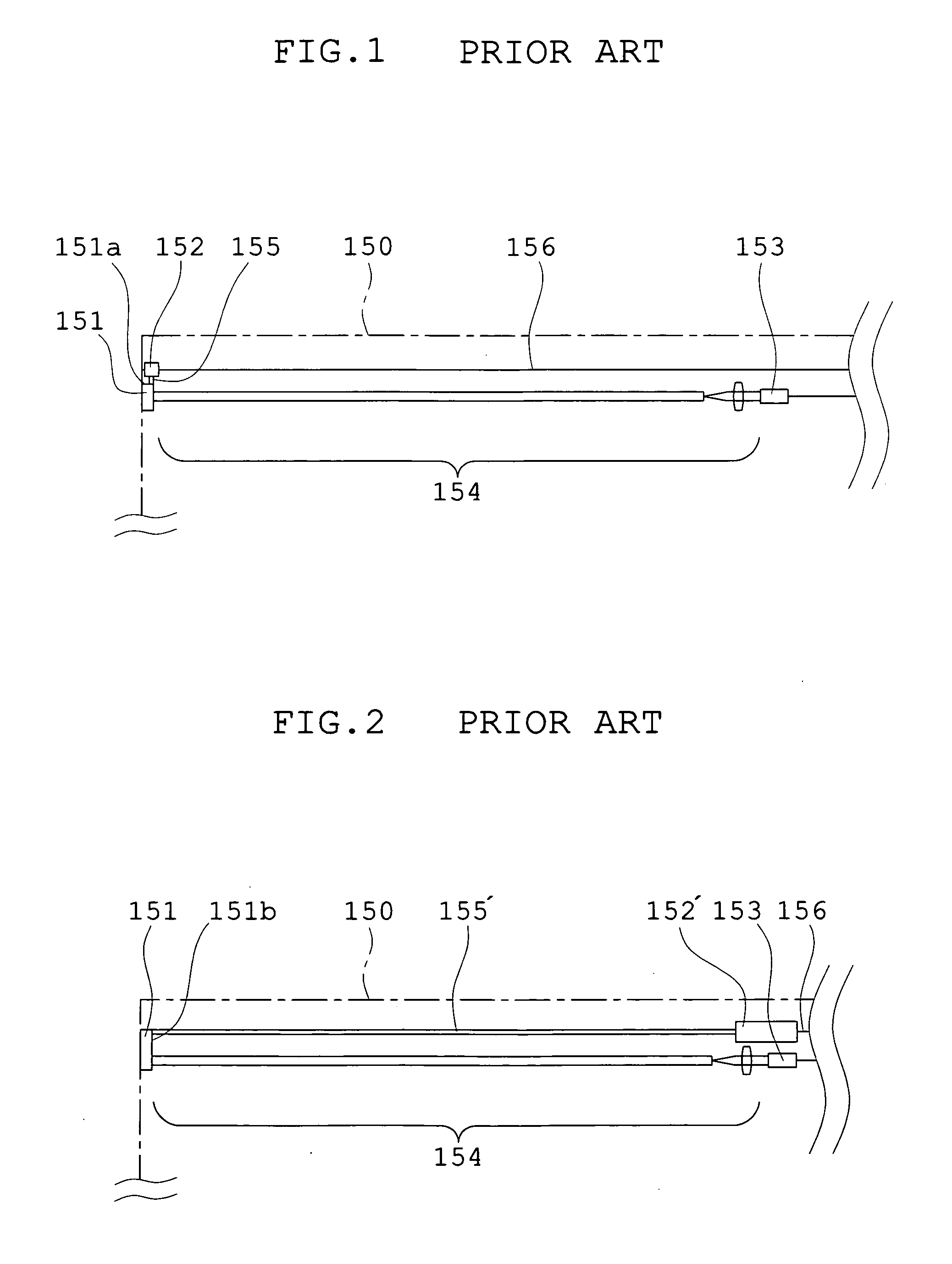
By the way, in an endoscope, failure of light source (LD) and the like may happen, and an optical fiber of a light guiding means may be broken.

Method used


Image

  • Illumination light detecting optical system and optical apparatus and endoscope apparatus provided with the same
  • Illumination light detecting optical system and optical apparatus and endoscope apparatus provided with the same
  • Illumination light detecting optical system and optical apparatus and endoscope apparatus provided with the same

Examples


embodiment 1

[0069]Next, concrete embodiments of the optical apparatus equipped with the illumination light detecting optical system according to the implementation modes mentioned above will be shown. FIG. 9 is an explanatory diagram showing an outlined outside view of an endoscope apparatus as an optical apparatus equipped with the illumination light detecting optical system of the first implementation mode according to the present invention. FIG. 10 is an explanatory diagram showing outlined constitution of the inside of the endoscope apparatus shown in FIG. 9.

[0070]The endoscope apparatus 31 is constituted that it has a main part of the apparatus 32, a monitor 33 by which an image by the endoscope is displayed, an thin-long, flexible insertion part 34 which is inserted into a space to be examined, a control unit 35 gripped by an operator connected to a rear anchor in the inserting direction of the insertion part 34, and a universal cord 36 having flexibility extended from the control unit 35...

embodiment 2

[0092]FIG. 14 is an explanatory diagram showing an outlined inside view of an endoscope apparatus as an optical apparatus equipped with the illumination light detecting optical system of the embodiment 2 according to the present invention. The endoscope apparatus of the embodiment 2 differs in that the return light of the illumination light is detected by two PD comparing with the endoscope apparatus 1 shown in FIGS. 9 and 10. Here, only differences will be explained. The same symbols are used to the same constitution in the embodiment 1, and the explanation of the same constitution will be omitted. As shown in FIG. 14, in the main part of the apparatus 32, light detecting parts 54a and 54b that are connected to a LD controlling part 50′ that is a light source controlling part; a photodiode (PD) 53a connected to the light detecting part 54a; a photodiode (PD) 53b connected to the light detecting part 54b; and an optical splitter 70 (a wavelength restricting component) arranged betwe...

embodiment 3

[0103]FIG. 15 is an explanatory diagram showing an outlined inside view of an endoscope apparatus as an optical apparatus equipped with the illumination light detecting optical system of an embodiment 3 according to the present invention. The endoscope apparatus of the embodiment 3 differs in that the light splitter is constituted with a mere half mirror in which the return light is divided in two directions without restricting wavelength to the return light which enters into the light splitter, in comparison with the endoscope apparatus shown in FIG. 13. Here, only this difference will be explained, the same symbols are used to the same constitution as the embodiment 1 and the embodiment 2, and the explanation will be omitted. As shown in FIG. 15, in the main part of the apparatus 32, a light detecting parts 54a and 54b that are connected to a LD controlling part 50″ that is a light source controlling part; a photodiode (PD) 53a connected to the light detecting part 54a; a photodio...


PUM


Abstract

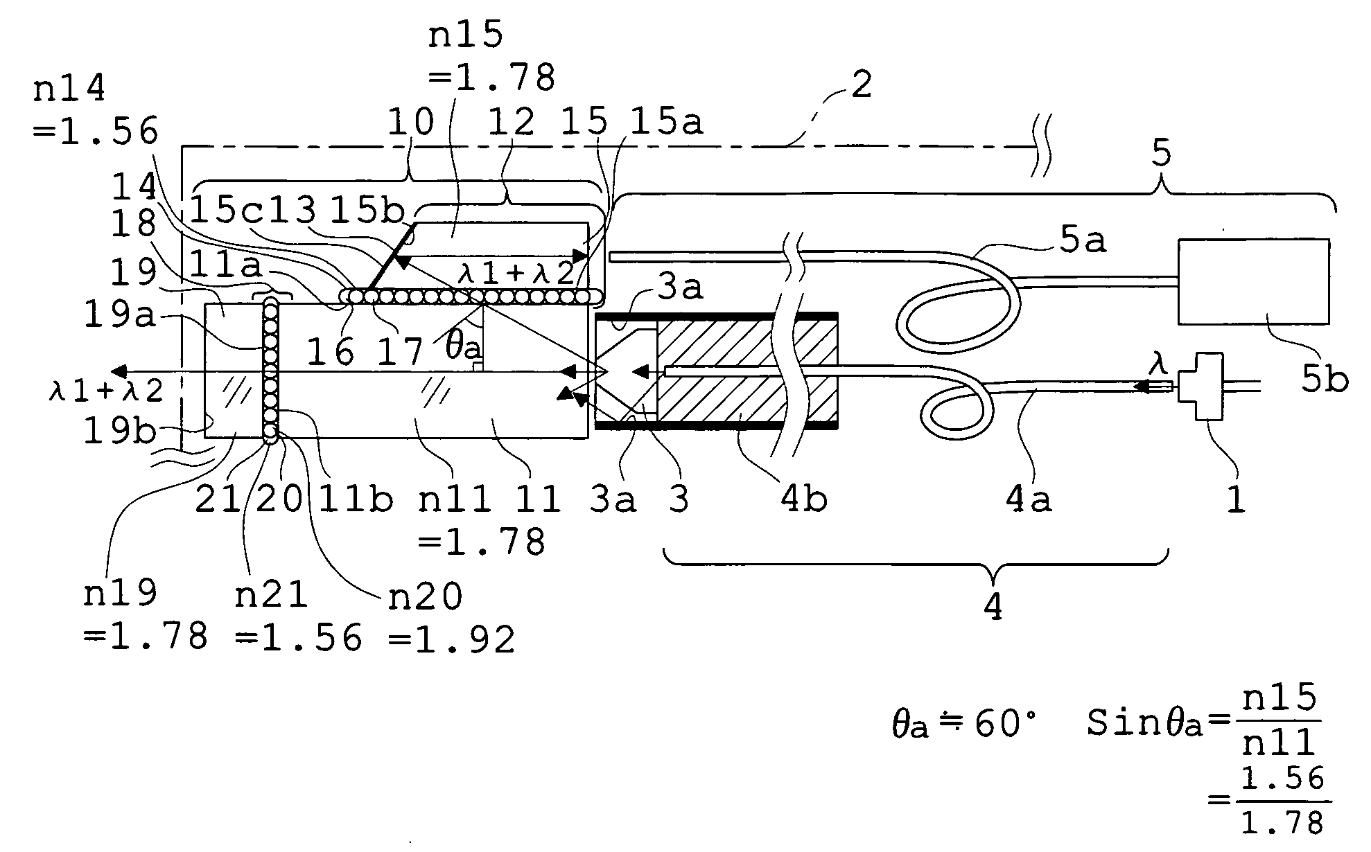
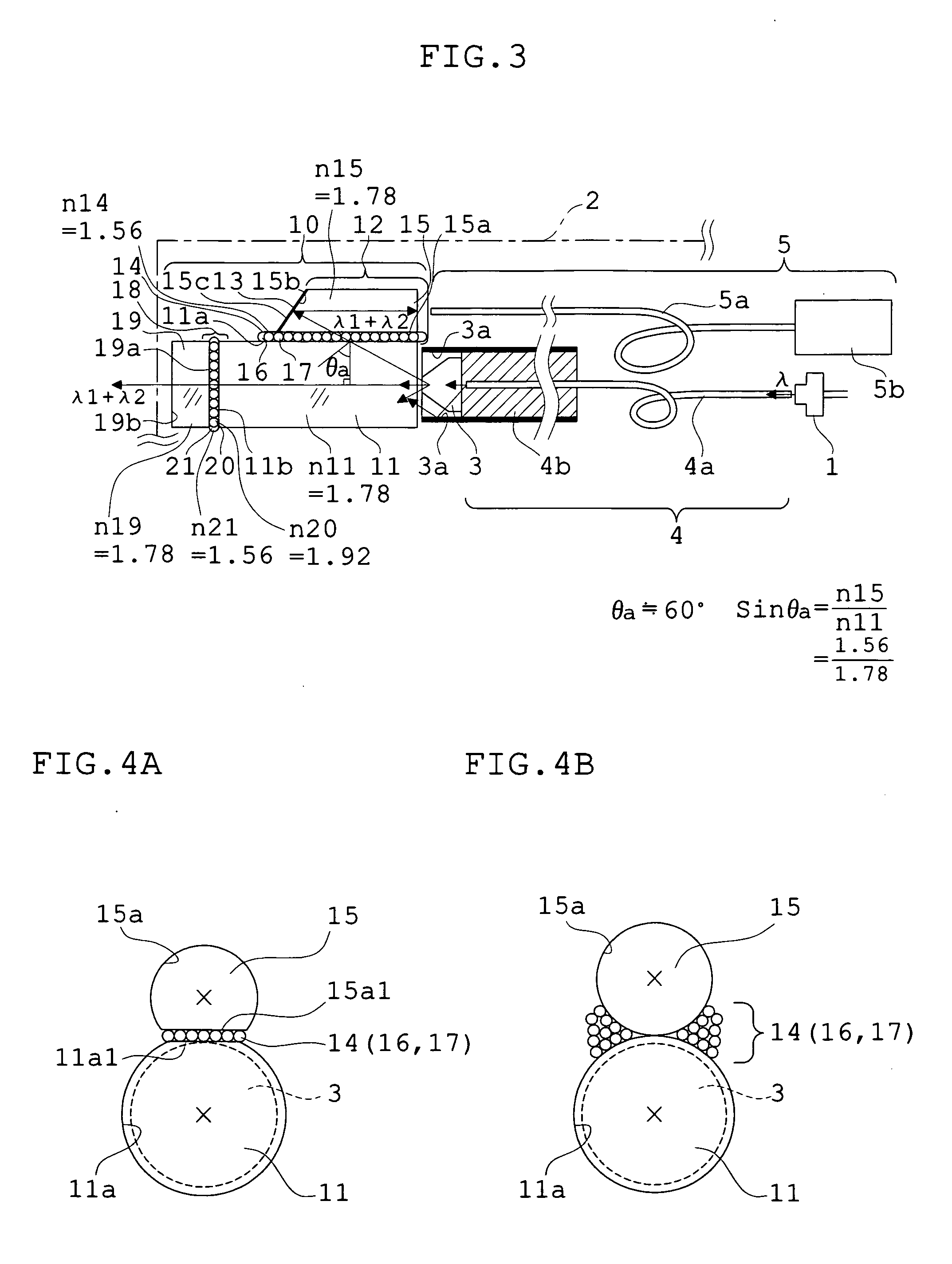
An illumination light detecting optical system that is used for an optical apparatus comprises a light emitting element which emits excitation light; an insertion part of a long-narrow-shape; a fluorescence luminescence component arranged near a top of the insertion part; an excitation light guiding means which leads the excitation light emitted from the light emitting element to the fluorescence luminescence component; and a light detecting means which detects return light which is a part of the illumination light. It is provided with a pillar-shaped transparent component for irradiating illumination light arranged coaxially at a forward position of the fluorescence luminescence component; an illuminating-light-extracting-means for extracting the illumination light which enters at an angle smaller than a total reflection angle to the side surface of the pillar-shaped transparent component from the pillar-shaped transparent component, out of the illumination light which is emanated in forward direction from the fluorescence luminescence component and enters into the inside of the pillar-shaped transparent component; and a deflecting means by which the extracted illumination light is directed toward the light detecting means.

Description

[0001]This application claims benefits of Japanese Patent Application No. 2007-129555 filed in Japan on May 15, 2007, the contents of which are hereby incorporated by reference.BACKGROUND OF THE INVENTION[0002]1. Field of the Invention[0003]The present invention relates to an illumination light detecting optical system and an optical apparatus and an endoscope apparatus provided with the same, for detecting abnormal illumination light in an illumination optical system in which for example, a fluorescence luminescence component is irradiated by LD light etc. as excitation light, and light which is mixed with the excitation light and fluorescence from the fluorescence luminescence component is used as illumination light.[0004]2. Description of the Related Art[0005]So far, an endoscope has been used for observation of a part which is difficult to observe from the outside in cases such as a medical treatment and / or diagnosis of inside of body of a patient in the field of medicine, an in...

Claims


Application Information

Patent Timeline
Patent Type & Authority Applications(United States)
IPC IPC(8): G01J1/58A61B1/06
CPCA61B1/043A61B1/05A61B1/07A61B5/0071A61B5/0084G02B6/0008G02B23/2423G02B23/2461A61B1/0653A61B1/0655
Inventor TAKAHASHI, SUSUMU
Owner OLYMPUS CORP
Why Eureka
Try Eureka