
Electric motor

a technology of electric motors and housings, applied in the direction of coupling device details, coupling device connections, multiple conductor connectors, etc., can solve the problems of difficult to form resilient engaging portions and difficult to form housings, and achieve the effect of simple structur

Inactive Publication Date: 2008-11-20
DENSO CORP
View PDF10 Cites 28 Cited by
  • Summary
  • Abstract
  • Description
  • Claims
  • Application Information

AI Technical Summary

Benefits of technology

[0017]The present invention addresses the above disadvantages. Thus, it is an objective of the present invention to pr

Problems solved by technology

However, when the removal limiting structure of Japanese Unexamined Patent Publication No. 11-3739 is applied to the motor of Japanese Unexamined Patent Publication No. 2003-111349, in which the terminals radially outwardly protrude, the following disadvantage may be encountered.
Therefore, it is difficult to form the resilient engaging portion by the cutting and pulling of the corresponding portion in the plate thickness direction in the terminal.
Furthermore, the engaging hole needs to be formed in the housing (the brush holder in Japanese Unexamined Patent Publication No. 2003-111349), so that it is difficult to form the housing.

Method used


Image

  • Electric motor
  • Electric motor
  • Electric motor

Examples


Embodiment Construction

[0028]An electric motor according to an embodiment of the present invention will be described with reference to the accompanying drawings. The motor of the present embodiment is applicable as a motor of a power seat of a vehicle, which is capable of adjusting a seat position (e.g., a fore and aft position and a vertical position of the seat) and a tilt angle of a seat back of the seat.

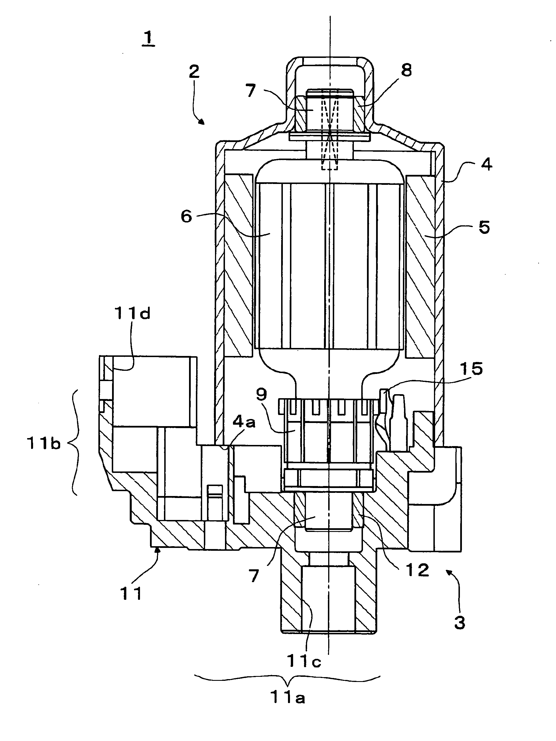
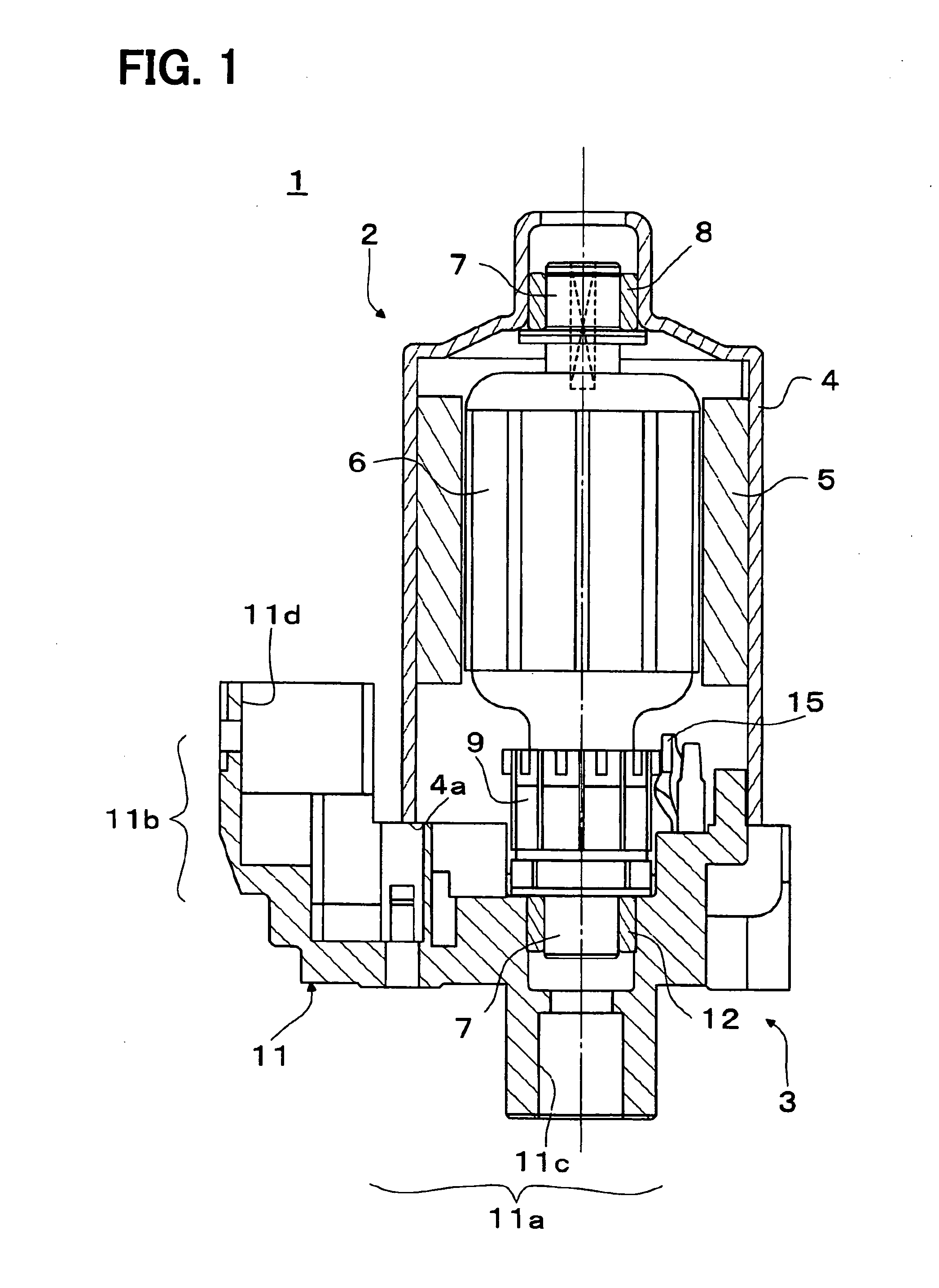
[0029]As shown in FIG. 1, the motor 1 includes a motor main body 2 and a brush holder 3.

[0030]The motor main body 2 includes a cup shaped yoke housing 4, which has an opening 4a. A plurality of magnets 5 is fixed to an inner peripheral surface of the yoke housing 4. An armature 6 is rotatably received in the yoke housing 4 at a location radially inward of the magnets 5. A rotatable shaft 7 is provided in the armature to extend in a longitudinal direction. A bottom center portion (a top center portion in FIG. 1) of the yoke housing 4 axially outwardly protrudes, and a bearing 8 is provided in this protr...


PUM


Abstract

In a terminal of an electric motor, a branch projects from a terminal connection on a side opposite from an extension. A projecting end side of the branch extends in an installation direction of the terminal, which is a direction for installing the terminal to a housing. The terminal is tiltable about a portion of the extension, which serves as a fulcrum, to cause abutment of the branch against a wall surface of the housing when the terminal connection receives a force in a direction opposite from the installation direction.

Description

CROSS REFERENCE TO RELATED APPLICATION[0001]This application is based on and incorporates herein by reference Japanese Patent Application No. 2007-128071 filed on May 14, 2007.BACKGROUND OF THE INVENTION[0002]1. Field of the Invention[0003]The present invention relates to an electric motor.[0004]2. Description of Related Art[0005]In general, in a case of an electric motor, which includes a rotatable shaft and an armature, a brush holder is fitted to an opening of a yoke housing of the motor to provide electric power for rotating the armature, and terminals are installed in the brush holder. One end of each terminal is connected to a corresponding brush, which is supported by the brush holder, and the other end of the terminal is connected to a terminal of an external connector, which is connected to an external power source. The electric power, which is received from the external power source, is supplied to the brushes to rotate the armature.[0006]In the prior art structure, in ord...

Claims


Application Information

Patent Timeline
IPC IPC(8): H02K5/14
CPCH01R11/05H01R13/112H01R2201/10H01R2201/26H02K5/148H02K5/225
Inventor HONDA, TETSUYATAKAHASHI, NOBUYUKI
Owner DENSO CORP
Learn More