Optical scanner and image forming apparatus

a technology which is applied in the field of optical scanner and image forming apparatus, can solve the problems of affecting the quality of images, so as to achieve high-quality writing and increase the layout freedom of optical systems

Inactive Publication Date: 2008-11-20
RICOH KK
View PDF43 Cites 46 Cited by
  • Summary
  • Abstract
  • Description
  • Claims
  • Application Information

AI Technical Summary

Benefits of technology

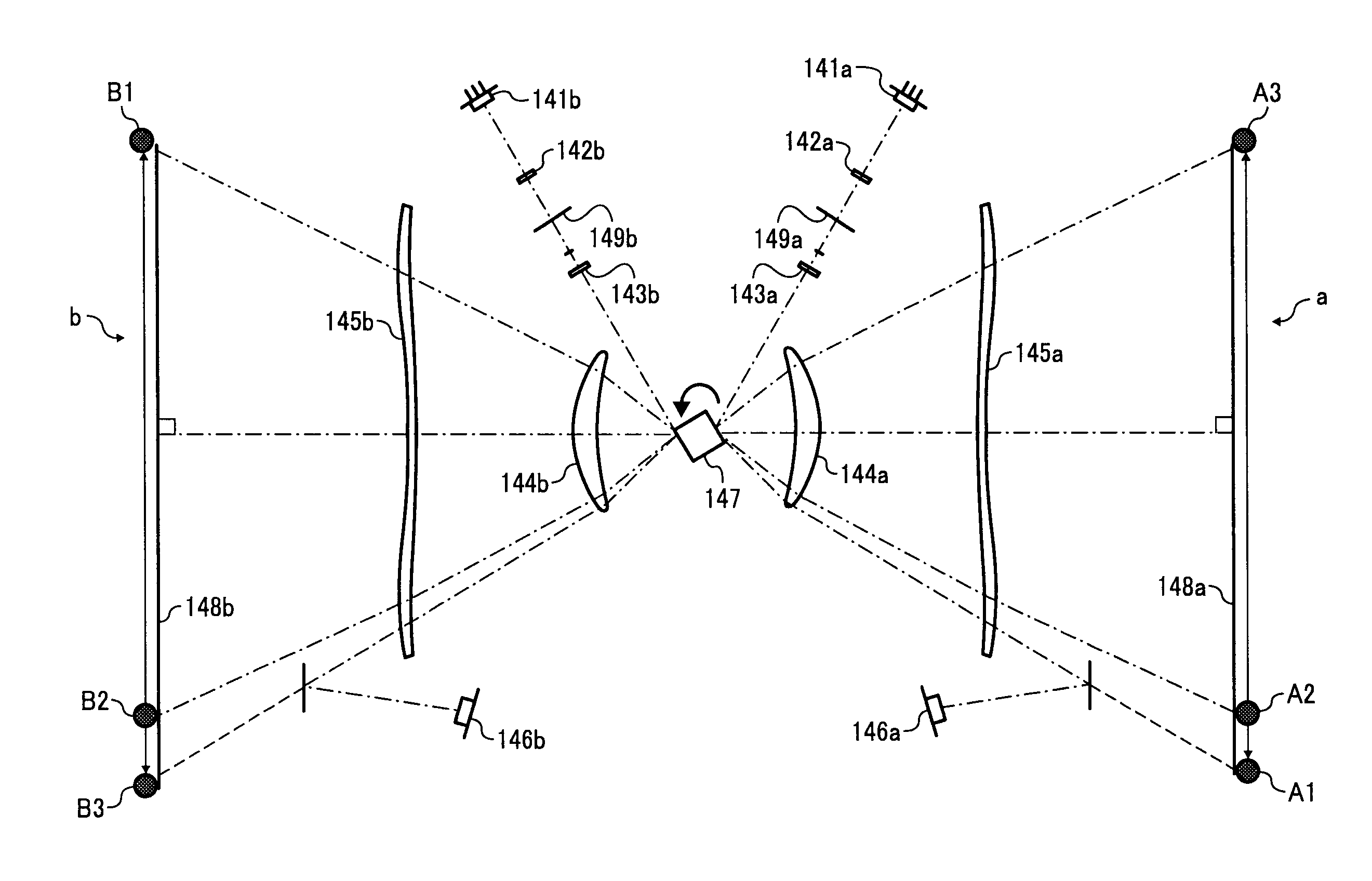
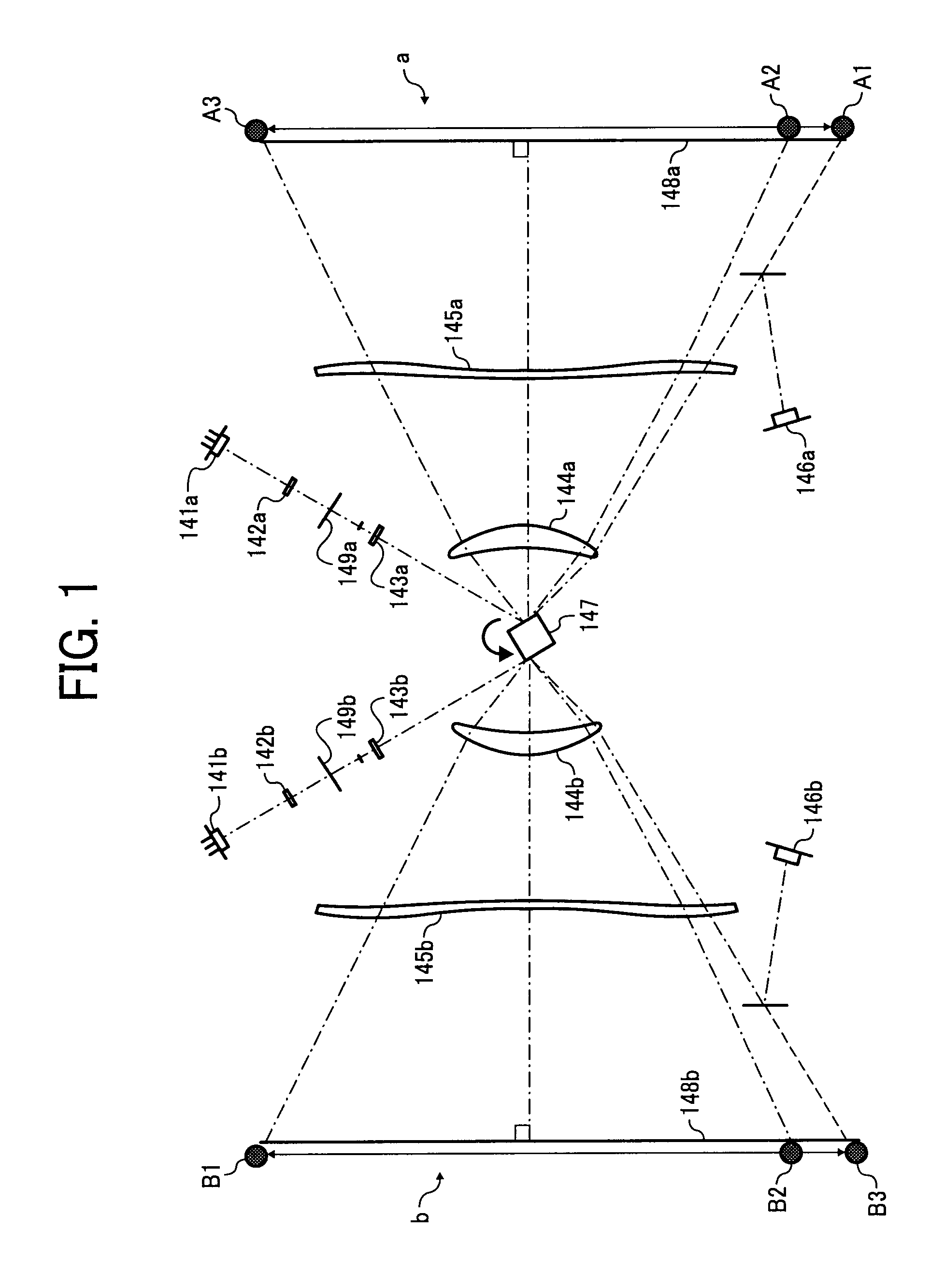
[0013]An object of the present invention is to provide an optical scanner in which layout freedom of optical systems is increased, and positional deviation of beam spots in a main scanning direction and degradation of curvature of an image in the main scanning direction and a sub scanning direction are prevented, so that high-quality writing can be performed.

Problems solved by technology

In the above-described configuration, four light paths are confusingly disposed in the optical scanner such that their arrangement is complicated and it is difficult to achieve a small size apparatus without interference.
However, if the number of optical elements is reduced, it is necessary to prevent degradation of image quality, which is caused by degradation of optical properties.
Therefore, a large size optical deflector is required, making it difficult to achieve high speed and long-term performance and there is a problem in that noise is generated due to rotation of the optical deflector.
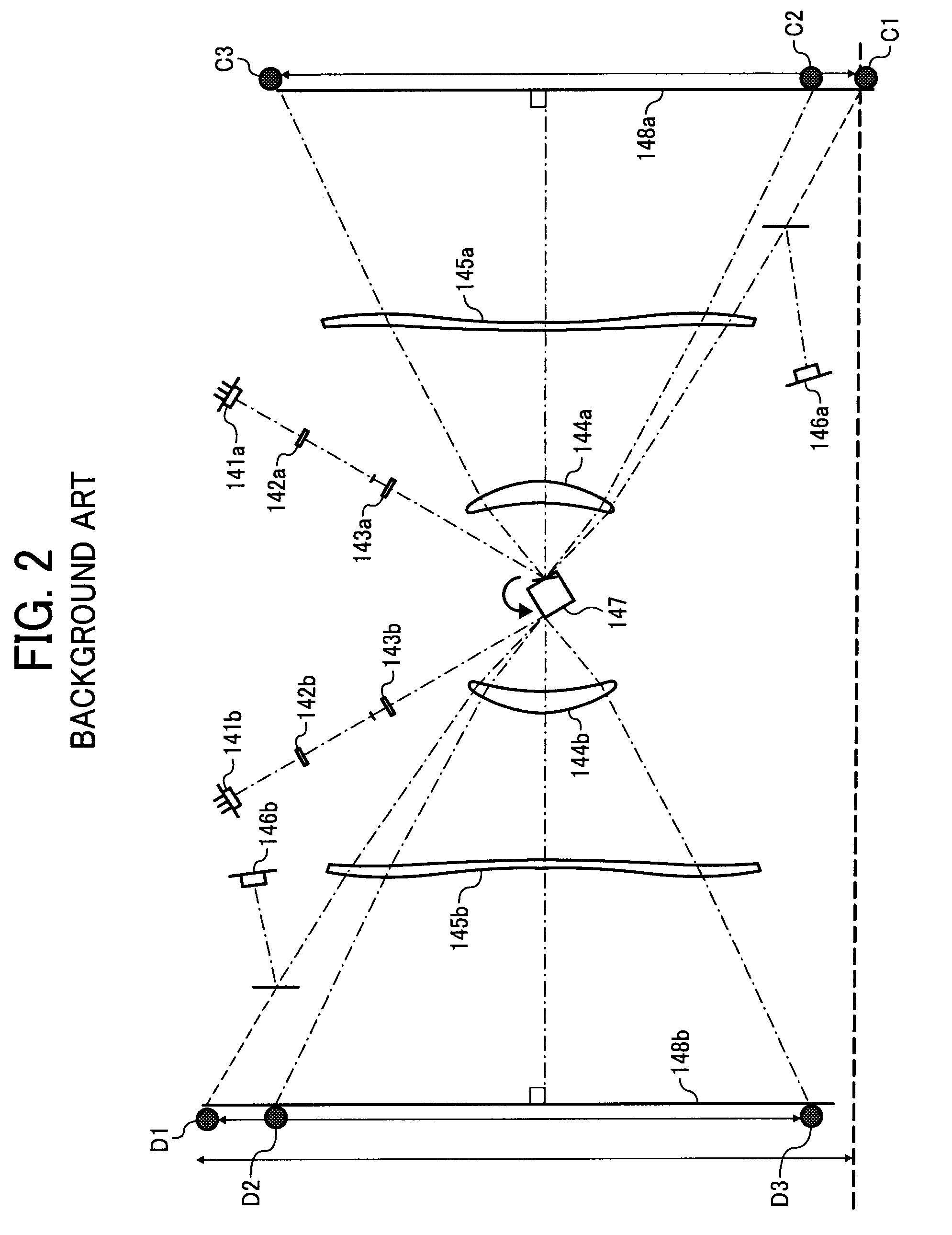
However, the reflection positions of the scanning optical systems are different, and therefore distances from the rotational center to the reflection surfaces are different so that the positional deviation of a beam spot in the main scanning direction due to the effect of sags and degradation of a curvature of an image in the main and sub scanning directions occur causing degradation of the output image.
In this method, although only one light-receiving element is provided so that layout freedom increases, variations in wavelength of the different light sources are not considered and time intervals become large so that accuracy is degraded and variations in writing start positions cause color deviations in an output image.
In the related arts described above, in the optical scanner in which scanning is performed at opposite sides of the optical deflector, it is not possible to obtain an optical scanner which performs high-quality writing while providing layout freedom of the light-receiving element to perform synchronization detection.

Method used


Image

  • Optical scanner and image forming apparatus
  • Optical scanner and image forming apparatus
  • Optical scanner and image forming apparatus

Examples


example

[0045]Next, an example of the optical scanner and the image forming apparatus according to the present invention will be explained.

[0046]FIG. 4 is a schematic perspective view illustrating an example of the optical scanner according to the present invention. The optical scanner includes semiconductor lasers (LD) 1, 1′, incident mirrors 2, 2′, coupling lenses 3, 3′, a half-mirror prism 4 as a light-flux dividing unit, cylindrical lenses 5a, 5b, 5c, 5d, a sound-proof glass 6, an optical deflector 7 such as a polygon mirror having four reflection surfaces, a first scan lens 8 (8a, 8b), optical path holding mirrors 9, a second scan lens 10 (10a, 10b), photoconductors 11a, 11b such as surfaces to be scanned, that is, image carriers, and an aperture 12.

[0047]Two divergent light fluxes emitted from the semiconductor lasers 1, 1′ are converted into weak convergent light fluxes, parallel fluxes, or weak divergent light fluxes. The light beams from the coupling lenses 3, 3′ pass through the a...


PUM


Abstract

An optical scanner includes a plurality of scanning optical systems each of which scans a different surface to be scanned and includes a light source configured to emit a light beam, an optical deflector having a plurality of reflection surfaces, and a synchronization detector configured to receive the light beam deflected by the optical deflector and detect a timing to scan an effective area of the surface to be scanned with the deflected light beam before a scanning is started or after the scanning is completed. The synchronization detector of one of a pair of scanning optical systems is disposed on a scanning end side to determine the scanning timing, and the synchronization detector of the other one of the pair of scanning optical systems is disposed on a scanning start side to determine the scanning timing.

Description

CROSS REFERENCE TO RELATED APPLICATIONS[0001]The present application is based on and claims priority from Japanese Application Number 2007-128272, filed on May 14, 2007, the disclosure of which is hereby incorporated by reference herein in its entirety.BACKGROUND OF THE INVENTION[0002]1. Field of the Invention[0003]The present invention relates to an optical scanner installed in an image forming apparatus in an electrophotographic system, and to an image forming apparatus such as a laser printer, a laser plotter, a digital copying machine, a plain paper facsimile, or a complex machine thereof, using the optical scanner.[0004]2. Description of the Related Art[0005]Recently, in an image forming apparatus in an electrophotographic system, which is known as a laser printer, the demands for a laser plotter, a digital copying machine, a plain paper facsimile, or a complex machine thereof, full-color, high quality, high speed, small size, and low cost have increased. In order to achieve su...

Claims


Application Information

Patent Timeline
Patent Type & Authority Applications(United States)
IPC IPC(8): G02B26/12G02B26/10
CPCB41J2/471G02B26/123G02B26/127H04N1/1135H04N1/12H04N1/506H04N2201/0471H04N2201/04713H04N2201/04744
Inventor ARAI, NOBUYUKIHAYASHI, YOSHINORIWATANABE, NAOTO
Owner RICOH KK
Why Eureka
Try Eureka