Optical disk medium and tracking method

a technology of optical disk and tracking method, which is applied in the field of optical disk medium and tracking method, can solve the problems of inability deterioration of track error signal quality, and decrease of signal, so as to achieve stable tracking control and increase the density of the track

Inactive Publication Date: 2008-11-20
HITACHI CONSUMER ELECTRONICS CORP
View PDF9 Cites 20 Cited by
  • Summary
  • Abstract
  • Description
  • Claims
  • Application Information

AI Technical Summary

Benefits of technology

[0011]As mentioned above, it is possible to provide an optical disk medium that is capable of performing stable tracking control while increasing track density of a three-dimensional pit selection type disk. The corresponding optical disk device, which achieves tracking control using a push-pull track error signal, is basically used. However, in the case of executing DPP tracking by the conventional optical disk medium, its corresponding switching means is provided so as to make it possible to provide an optical disk device corresponding to either medium.
[0012]The optical disk medium and the optical disk device of the present invention make it possible to provide a large-capacity disk system by use of a super-resolution effect.

Problems solved by technology

If the track pitch is reduced, amplitude of a track error signal decreases in the pull-push method and quality of the track error signal deteriorates due to an influence of crosstalk with an adjacent track and the like in the DPD method, and therefore stable tracking control cannot be achieved in either case.
Moreover, in the DPD method, if the recording mark (pit) is reduced, a phase difference occurred at the edge portion decreases, and as a result, a stable track error signal cannot be obtained.
For the aforementioned reason, it is considered to be difficult to further narrow the track.

Method used


Image

  • Optical disk medium and tracking method
  • Optical disk medium and tracking method
  • Optical disk medium and tracking method

Examples


Embodiment Construction

[0038]Even if stable tracking is achieved by the present invention, there is no point in doing so if quality of readout data deteriorates due to crosstalk from an adjacent track caused by track narrowing of data track. In addition, there is a need to provide a specific configuration of a disk and a readout method thereof.

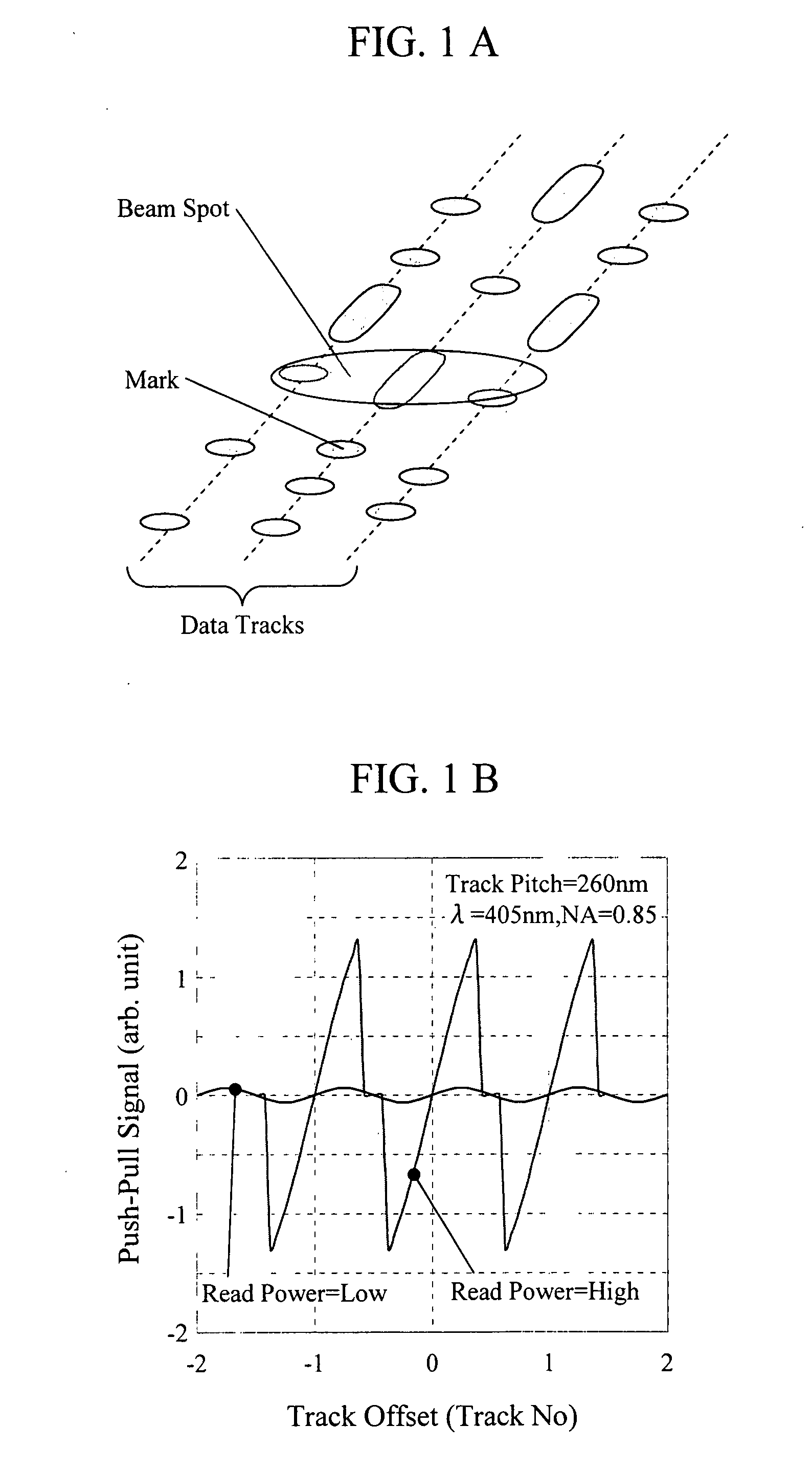
[0039]The following will specially describe problems and means for solving the problems in order to implement the optical disk medium and the tracking method of the present invention. The problems to implement the present invention include: (1) a reduction in crosstalk between data tracks caused by narrowing data track; (2) provision of specific disk configuration and disk manufacturing method; and (3) quantification of an effect of the present invention with respect to a push-pull signal obtained by the conventional method. The following will explain the means for solving the aforementioned problems.

[0040](1) Reduction in crosstalk between data tracks caused by nar...


PUM

PropertyMeasurementUnit
wavelengthaaaaaaaaaa
drive currentaaaaaaaaaa

Abstract

A super-resolution material is formed in only a data pit, in a low temperature state of the super-resolution material, reflectivity of each of a pit portion and a space portion and an optical phase difference therebetween are set to be sufficiently small, in a high temperature state, and at least the optical phase difference between the pit and the space is set to be larger than the aforementioned value in an absolute value. Accordingly, by conducting irradiation with an appropriate read power by which substantially only one data track width can be heated to a high temperature state, a good push-pull signal can be obtained even with a track pitch being less than a diffraction limit. At the same time, by an optical device having functions such as a switching means with a DPP type, an offset correcting means of the push-pull signal due to lens shift, a shaping means of the push-pull signal, a learning means of read power, and the like, there is provided an optical disk device that corresponds to the optical disk medium of the present invention and achieves an increase in capacity.

Description

CLAIM OF PRIORITY[0001]The present application claims priority from Japanese application JP 2007-131124 filed on May 17, 2007, the content of which is hereby incorporated by reference into this application.BACKGROUND OF THE INVENTION[0002]1. Field of the Invention[0003]The present invention relates to an optical disk that forms a recording mark having a different physical characteristic from that of the other portion on a recording medium to store information and an optical disk device that reads information from the medium.[0004]2. Description of the Related Art[0005]The optical disk medium includes various types such as a CD-R / RW, DVD-RAM, DVD±R / RW, Blu-ray Disc (hereinafter referred to as BD), HD DVD, and the like, and such an optical disk medium that includes one with two data layers has come into general use. A so-called DVD super multi-drive, which is provided for writing / reading on / from CD-R / RW, DVD-RAM and DVD±R / RW, has widely available as the corresponding optical disk devi...

Claims


Application Information

Patent Timeline
Patent Type & Authority Applications(United States)
IPC IPC(8): G11B7/26G11B7/24062
CPCG11B7/0901G11B7/0938G11B7/094G11B7/24G11B7/24079G11B7/24085
Inventor MINEMURA, HIROYUKISHINTANI, TOSHIMICHIANZAI, YUMIKOETO, SOICHIRO
Owner HITACHI CONSUMER ELECTRONICS CORP
Why Eureka
Try Eureka