[0007]The present invention speeds the process, adds a layer of safety, and allows rapid conversion between a needle / syringe system and a needleless / syringe system, thus allowing an operator to move seamlessly between both systems while minimizing needle stick risk. In particular, the current invention provides for the
insertion of the syringe into the needleless system with no exposed
sharp point that may inadvertently lead to a
skin puncture.
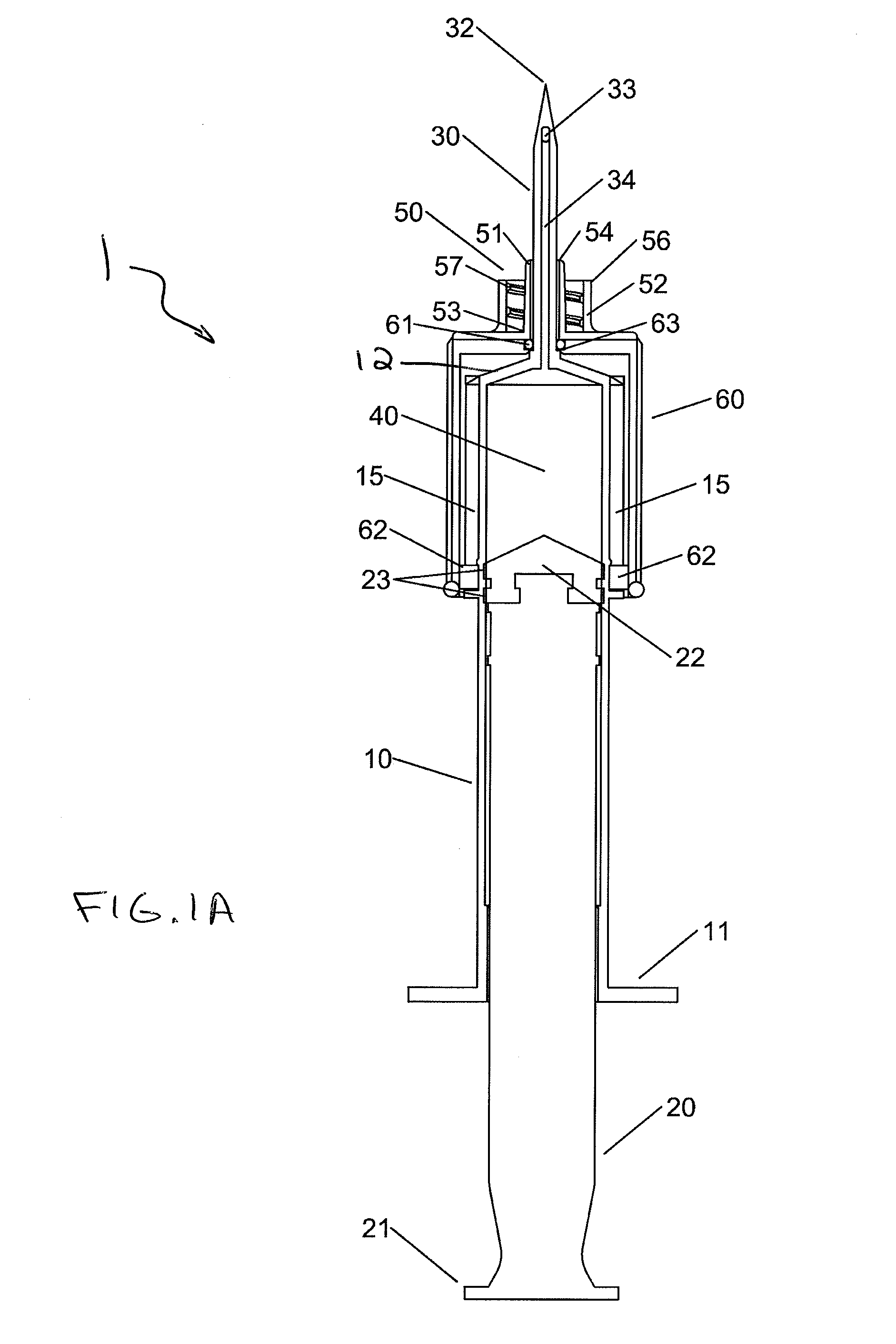
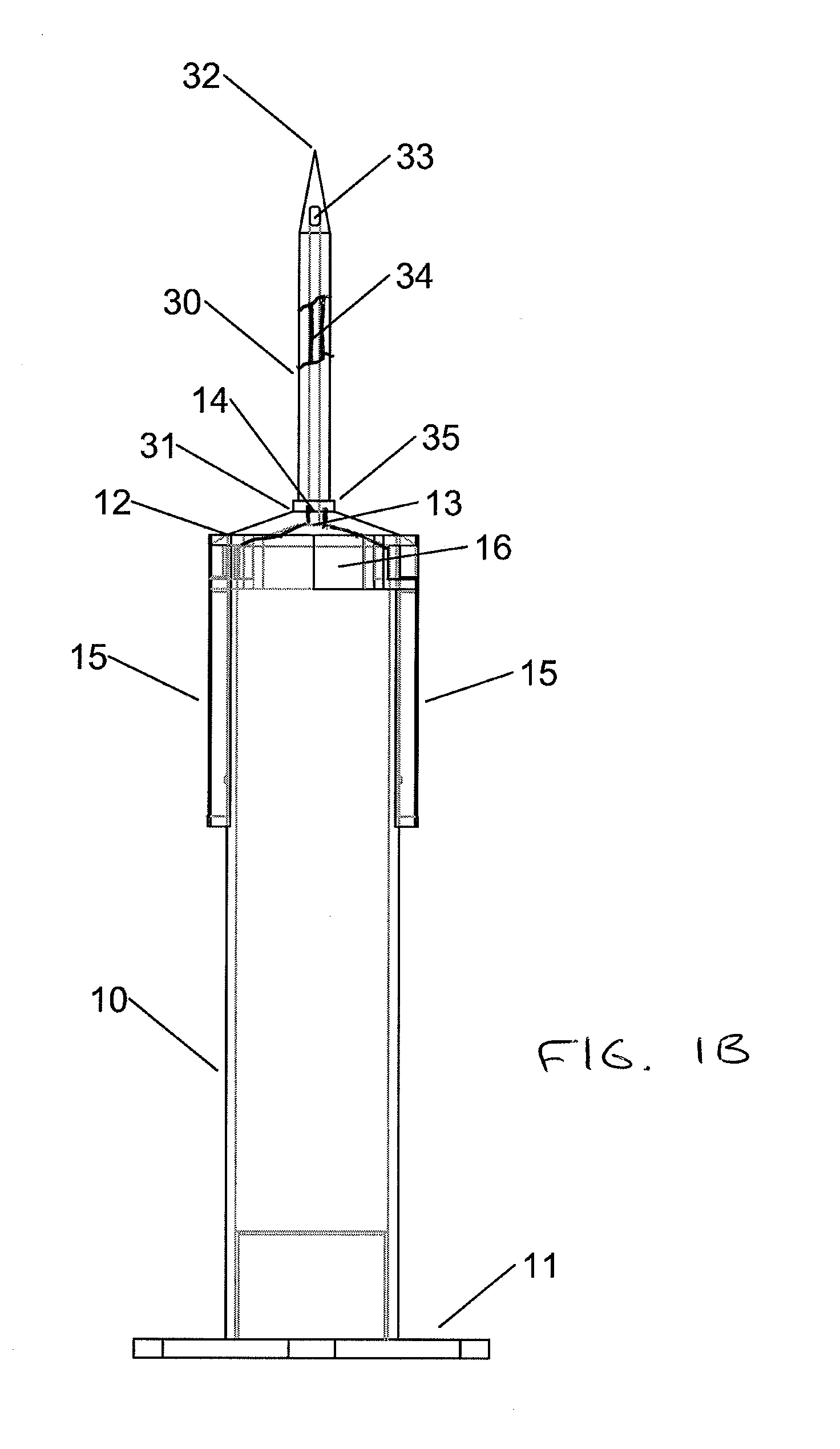
[0008]The system allows for a collar or sheath with an attached fluid port to slide over the fixed needle at the end of the syringe and reversibly lock in an advanced position creating a functionally needleless adaptor for
interfacing with the needleless tubing systems. The system also allows for retraction of the collar to
expose the fixed needle at the end of the syringe for
puncturing medication bottles.
[0010]In one aspect, the invention relates to a syringe system including a syringe
barrel defining an
interior space, a syringe
plunger slidably disposed within the syringe
barrel, a needle coupled to a distal end of the syringe
barrel and in fluid communication with the
interior space, a collar slidably disposed about the syringe barrel, and a fluid port disposed at a distal end of the collar. The collar can be coupled to the syringe barrel to prevent inadvertent disengagement therefrom. The fluid port is configured to interface with a needleless tubing system.
[0015]In still further embodiments of the syringe system, the collar is guided between the first position and the second position by a thread disposed on an external
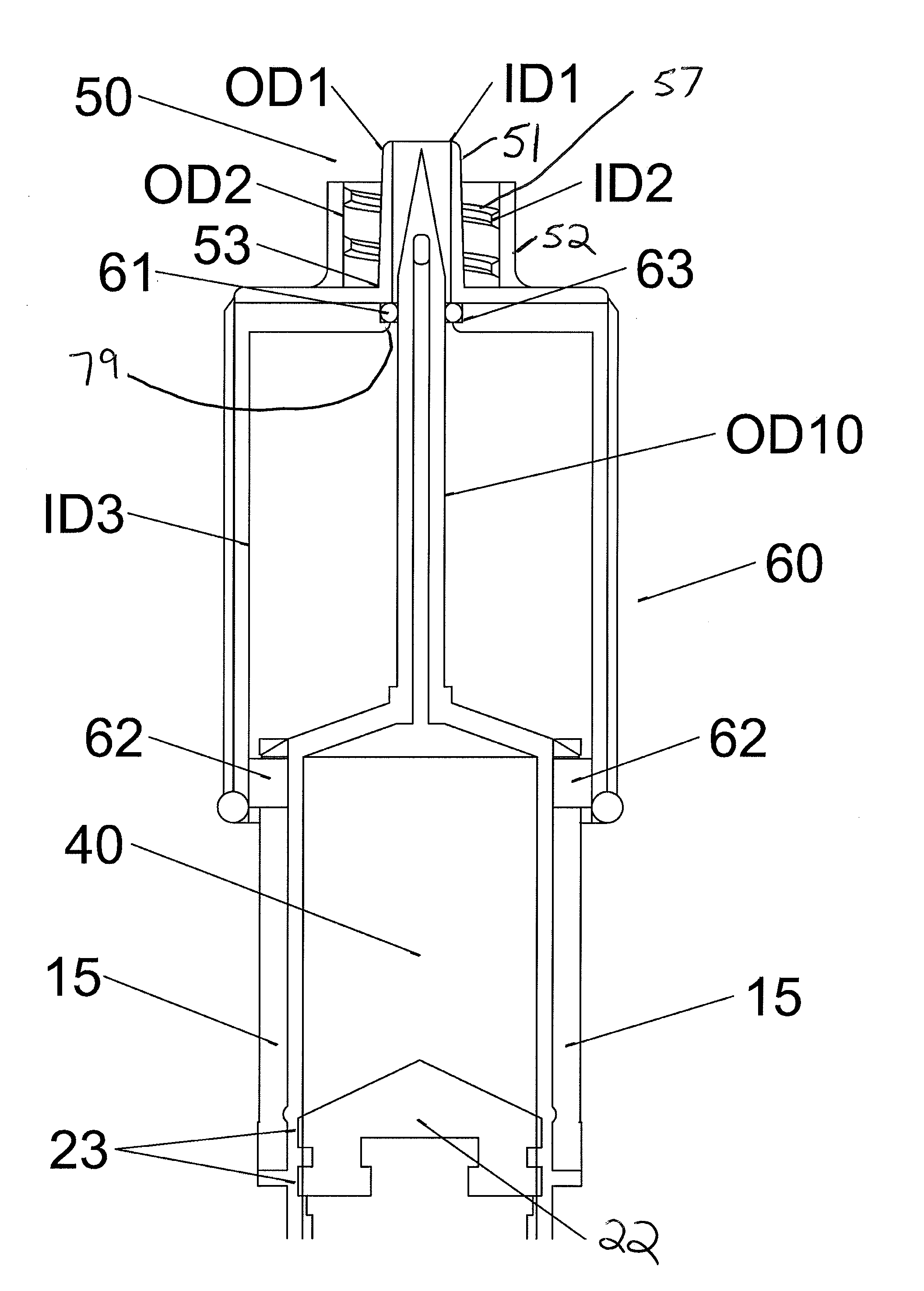
diameter of the syringe barrel, for example as opposed to sliding on the rails. The fluid port can be configured for attachment of a secondary needle, for example, by threaded engagement. The secondary needle can provide a different needle configuration and / or size for a particular application and can be attached to the syringe in its extended position. In addition, the collar can be biased in at least one of the first position and the second position to prevent the inadvertent movement of the collar when in use. In one embodiment, the collar includes a spring mechanism for biasing the collar in the second position. For example, the spring mechanism can be a spring or other resilient member disposed within the collar between a distal end of the syringe barrel and a distal interior end of the collar, thereby biasing the collar in the second, advanced position. The collar can be forced back against the spring to the first, retracted position and locked in place. Such an arrangement will
fail safe with the collar in the advanced position, thereby covering the needle.
[0016]Moreover, the fluid port may conform to at least one of ISO standard 594-1 and 594-2. The collar can be removable from the syringe barrel and interchangeable with a second collar with an alternative fluid port. This arrangement allows the syringe
assembly to be customized for the particular needleless tubing system to which it will interface. In one embodiment, the collar can be snap fit onto the syringe barrel and can be removed by flexing the collar such that the protuberance(s) are moved out of the slotted rail(s). Once the protuberances clear the slotted rail, the collar can be rotated and slid off of the syringe barrel. In another embodiment, a
distal portion of the collar can include an internal channel for receiving at least a
distal portion of the needle. The channel can be formed in the distal end of the collar or can include an additional cylindrical body formed coextensively with the collar and defining the channel running therethrough. The needle can be moved through the channel when the collar is retracted into the first position. The collar can further include an O-ring disposed in an annular groove formed in an internal surface of the channel. The O-ring provides a seal between an outer
diameter of the needle and an inner
diameter of the channel for the passage of a fluid between the syringe barrel and the needleless tubing system, without leakage. The seal facilitates generating a suction at the distal end of the collar when the collar is in the extended position and the syringe
plunger is drawn back to draw fluid into the syringe barrel. Generally, the syringe
plunger can be extended and retracted to draw in and dispense fluid, respectively, through the distal end of the collar through the fluid port between the syringe and the needleless system. In one embodiment, the friction between the O-ring and the needle will prevent or at least impede movement of the collar. Additionally, in an embodiment where the needle expands at its base, the increased
interference fit between the outside diameter of the needle and the inside diameter of the O-ring will further secure the collar in place.
[0017]In yet another embodiment of the syringe system, the syringe barrel has a generally circular cross-sectional shape and the collar has a generally elliptical internal cross-sectional shape, which provides for a slight interference between the outside diameter of the syringe barrel and the inside surface of the collar. This arrangement can provide sufficient
surface tension between the collar and syringe barrel to prevent sliding movement between the collar and the syringe barrel. A light pressure can be applied to the collar to deform the internal cross-sectional shape of the collar from generally elliptical to generally circular and of a larger diameter than the outside diameter of the syringe barrel to enable slidable movement therebetween. For example, the operator applies a squeezing force to the collar with one hand to deform the collar and initiates sliding of the collar with the other hand, thereby sliding the collar along the syringe barrel between the first and second positions. When the force is removed, the collar returns to the generally elliptically shaped internal cross sectional shape which provides a partial
interference fit with the outside diameter of the syringe barrel, which provides sufficient
surface tension to prevent movement of the collar.


