
System and Method for Facilitating Electronic Financial Transactions Using a Mobile Telecommunication Device

a mobile telecommunication device and electronic financial transaction technology, applied in the field of system and method for facilitating electronic financial transactions, can solve the problems of low security level, transmission over the system, and significant risk for users of such a system

Inactive Publication Date: 2008-11-20
CONCEPTM
View PDF6 Cites 90 Cited by
  • Summary
  • Abstract
  • Description
  • Claims
  • Application Information

AI Technical Summary

Benefits of technology

[0054]A particularly advantageous feature of the above system is the message processing program module. This module enables the transaction to be verified locally by the customer on his or her mobile communication device (eg a mobile phone). In this way, the secret identification parameter (eg a personal identification number (PIN)) is not transmitted to the server. Accordingly, there is no possibility of the PIN being intercepted in transit. Similarly, the server does not contain any reference to the secret identification parameter and there is therefore no prospect of the parameter being accessed or viewed on the server by an unauthorised person. The security of the above system is further enhanced by the encryption of the transaction verification message and by the digital signature which may optionally be attached to the message.
[0092]A beneficial feature of the above system is the relative simplicity of the system server and the message flow to and from this server.
[0109]As noted above, this program module is a unique feature which substantially improves the security of the abovementioned system. Incorporated in the program module is means for enabling self-verification by a user completely at the user's mobile device, without any message (containing the secret identification parameter) having to be sent from the mobile device to the system server. The program module also provides for the verification message to be encrypted and (optionally) digitally signed which substantially improves the security of the system.
[0111]The security of the system is further enhanced by forming the secure verification message, sent from the mobile communication device to the system server, of a binary data stream.

Problems solved by technology

Such a system has a very low level of security and, therefore, users of such a system run a significant risk that messages transmitted over the system (which may include confidential identifying criterion, such as a PUV) may be intercepted and used fraudulently.
A problem with this system is that it also involves a low level of security with the relevant bank account details being transmitted and subject to interception by unauthorised persons.
However, this system has a number of disadvantages, namely:1. The telecommunication and account management functions are performed by the same server.
In order for this system to work as claimed, it has to perform both telecommunication and banking functions.2. Having the telecommunication and account management functions performed by the same server compromises the security of the system and renders the accounts of users more vulnerable to being accessed by unauthorised persons than is the case if the telecommunication and account management functions are performed by (more secure) server which is separate from the telecommunication server.
Again, this gives rise to a low level of security with the danger that the PIN could be intercepted by an unauthorised person.5. The system is very network-dependent and, for it to work effectively, a complex arrangement of data storage means and checks need to be conducted to identify the type of mobile phone of the user and then to determine the relevant network on which the mobile phone operates.6. The system involves a complicated and expensive arrangement of verification means, databases, account management means, confirmation messages and acceptances messages which interact in a complex manner.
This has the effect of slowing down the system and increasing the likelihood of errors or failures occurring.

Method used


Image

  • System and Method for Facilitating Electronic Financial Transactions Using a Mobile Telecommunication Device
  • System and Method for Facilitating Electronic Financial Transactions Using a Mobile Telecommunication Device
  • System and Method for Facilitating Electronic Financial Transactions Using a Mobile Telecommunication Device

Examples


example

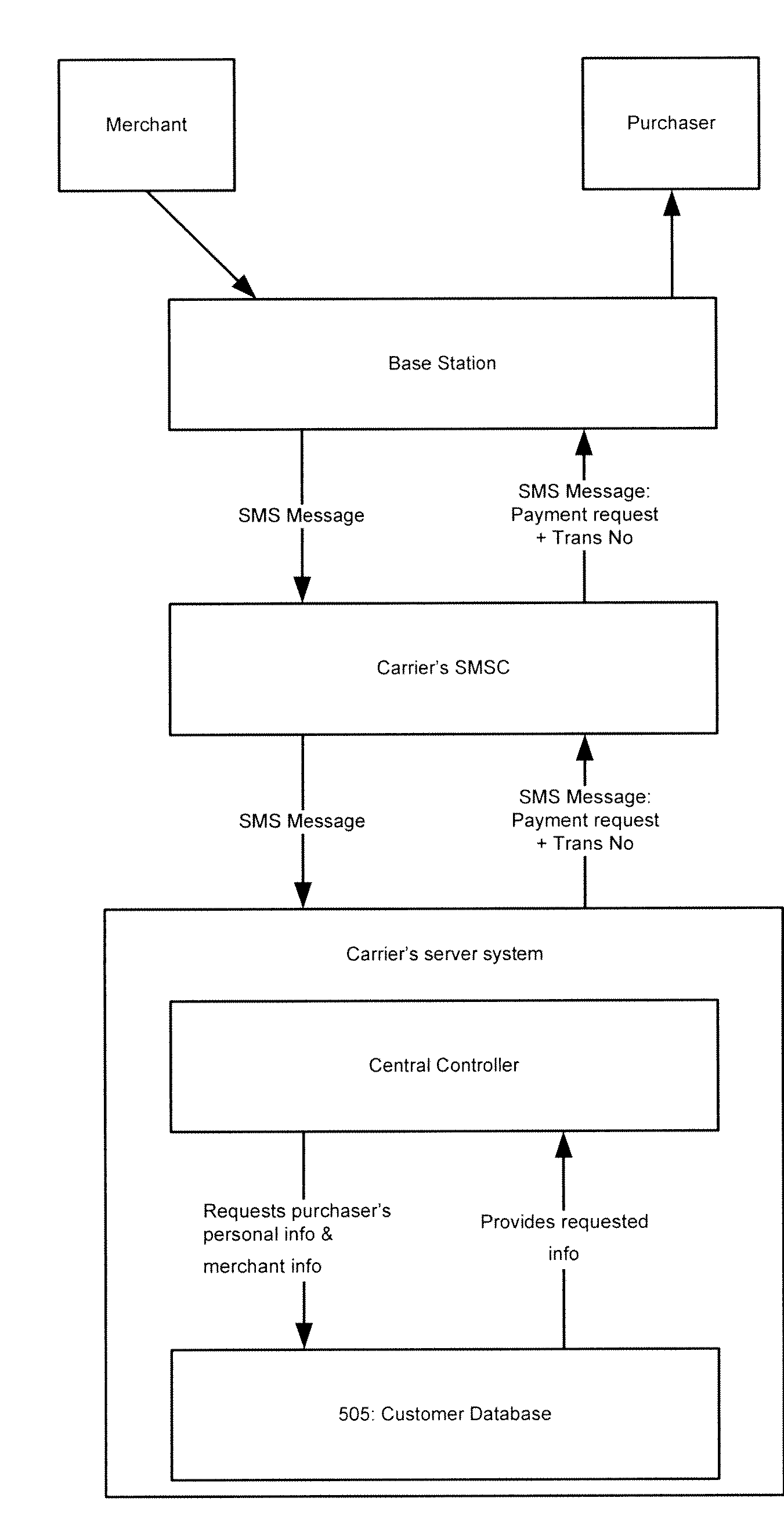
[0273]FIGS. 9 to 14 are logic flow diagrams showing the flow of messages within the system of this invention. The steps shown in a hexagonal border are performed within the Gateway Receiver and steps contained in rectangular borders are performed in the Gateway Core. The system server receives a request from the supplier device (“M Payment Request Initialisation Tool”) to initiate a transaction. The message then undergoes certain checks within the carrier server. A transaction identifier (“MTransID”) is added to the message and the message can then be sent.

[0274]Alternatively (as shown in FIG. 9), before the message is sent, the system server can check on the availability of any benefits (eg coupons, product / service offerings and the like) being offered by the supplier. In order to do this, the system server checks its database records and if a particular benefit is found, then the processing steps are implemented.

[0275]The benefit processing steps are shown in FIGS. 10 and 11. If a...


PUM


Abstract

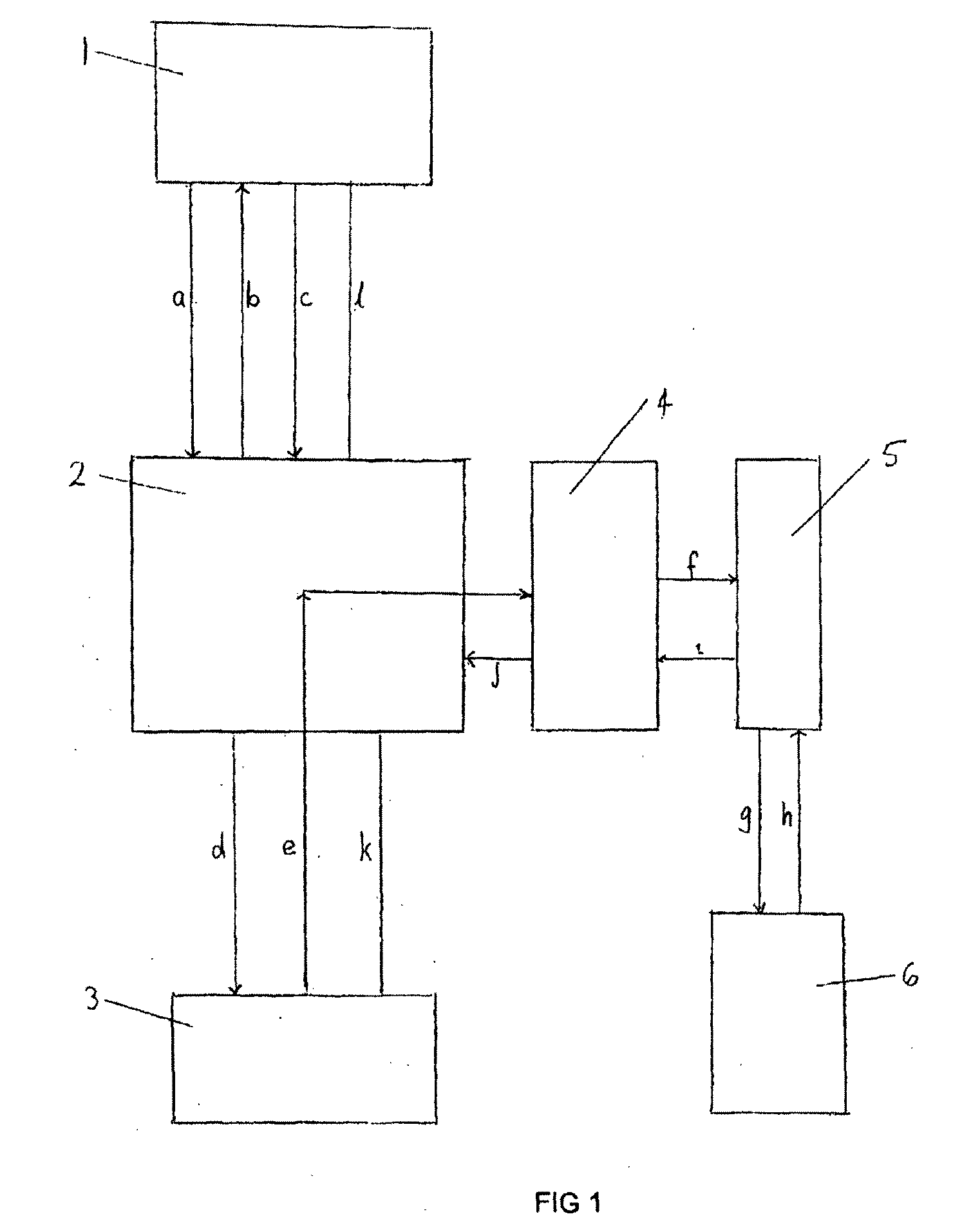
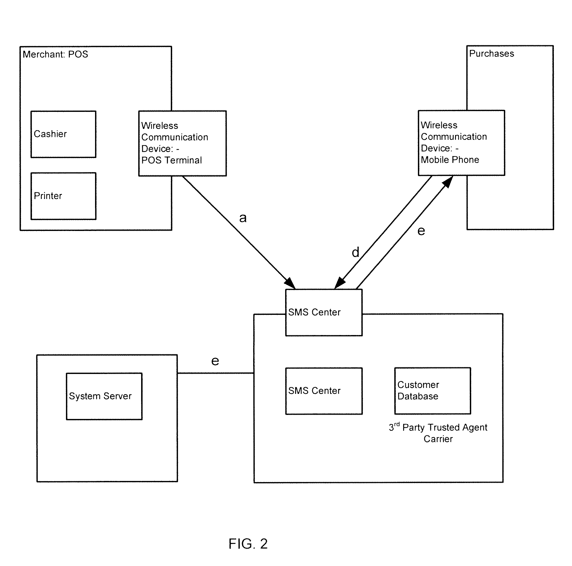
A transaction processing system for processing a transaction between a supplier and a customer, said system comprising a supplier device for initiating the transaction, a system server and a mobile communication device, said device containing a message processing program module for enabling local verification of the transaction within the mobile device, wherein a transaction message is sent from the supplier device to the system server, a message requesting payment for the transaction is sent from the system server to the mobile communication device, the transaction is authorised and verified at the mobile telecommunications device from which a verification message is sent back to the system server, and the transaction is then processed.

Description

TECHNICAL FIELD[0001]The present invention relates to a system and method for facilitating electronic financial transactions. More particularly, one aspect of the invention relates to a system and method for facilitating electronic financial transactions between a goods or services provider and a consumer using a system server in communication with a supplier device, a mobile communication device and a transaction processing server.[0002]The present invention also relates to a system and method for sending service suggestion messages to mobile communication devices. It also relates to a method of confirming the validity of a service suggestion.BACKGROUND ART[0003]A number of proposals have been made to enable electronic financial transactions to be conducted using mobile phones. Some of these involve the transmission of a customer's mobile telephone number over the internet to a supplier's website. In such a system, the supplier's site transmits the telephone number, a supplier iden...

Claims


Application Information

Patent Timeline
Patent Type & Authority Applications(United States)
IPC IPC(8): G06Q30/00H04L9/32G06Q40/00G06Q20/20G06Q20/32G06Q20/36G06Q20/38G06Q20/40G06Q20/42G06Q30/02G06Q30/06H04W4/00H04W4/24H04W8/26H04W12/08H04W12/10
CPCG06Q20/20H04W12/10G06Q20/3223G06Q20/3229G06Q20/3255G06Q20/3674G06Q20/382G06Q20/40G06Q20/42G06Q30/0225G06Q30/06G06Q30/0603H04L63/10H04L63/12H04M15/68H04M2215/0196H04W4/00H04W4/24H04W8/26H04W12/08G06Q20/32H04W12/082
Inventor LEUNG, GARYLEE, RUDOLPHCHENG, KEVINCHUI, PETERMITCHELL, ANDREWMEKERTICHIAN, SHAHENFUNG, RAYMONDCHAN, JOSEPH
Owner CONCEPTM
Learn More