
Structure for resetting a hypertransport link in a blade server

a technology of blade server and hypertransport link, applied in the direction of instruments, digital computers, computing, etc., can solve the problem that the computer system has evolved into extremely complicated devices

Inactive Publication Date: 2008-11-20
IBM CORP
View PDF40 Cites 4 Cited by
  • Summary
  • Abstract
  • Description
  • Claims
  • Application Information

AI Technical Summary

Benefits of technology

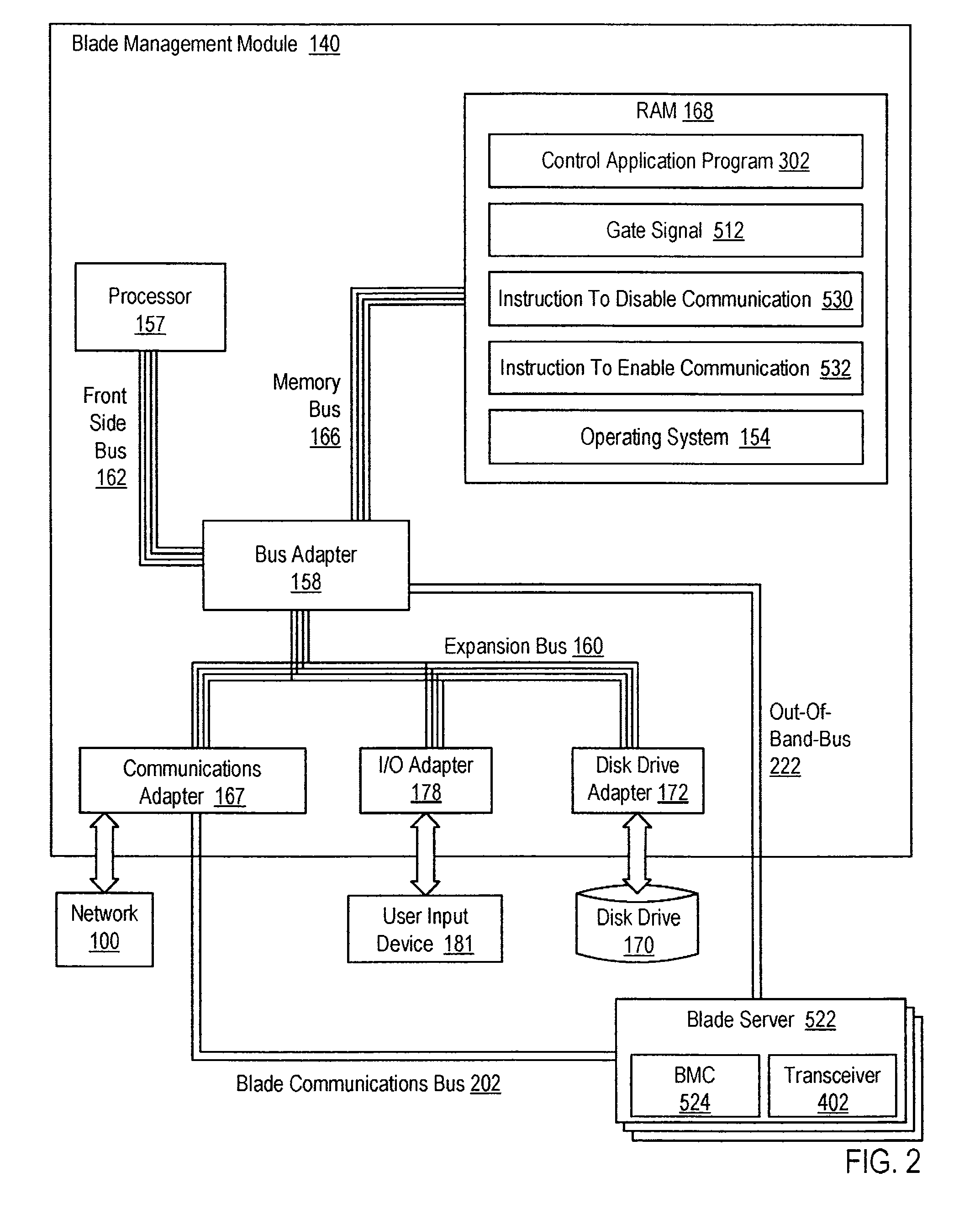
[0008]In one embodiment, a design structure embodied in a machine readable storage medium for at least one of designing, manufacturing, and testing a design is provided. The design structure generally includes an apparatus for resetting a HyperTransport link in a blade server. The blade server generally includes a blade processor, a reset sync module, and a baseboard management controller. The blade server can be installed in a blade center. The blade center generally includes a blade management module, wherein the blade management module can be coupled to the baseboard management controller by a blade communication bus. The HyperTransport link generally includes a bidirectional, serial / parallel, high-bandwidth, low-latency, point to point data communications link. The apparatus generally includes a computer processor and a computer memory operatively coupled to the computer processor. The computer memory can have computer program instructions disposed within it that are capable of reassigning, by the blade management module, a gate signal from enabling a transceiver to signaling a HyperTransport link reset, sending, by the blade management module to the reset sync module on an out-of-band bus, the gate signal, and in response to the gate signal, sending, by the reset sync module to the blade processor, HyperTransport reset signals.

Problems solved by technology

Since that time, computer systems have evolved into extremely complicated devices.

Method used


Image

  • Structure for resetting a hypertransport link in a blade server
  • Structure for resetting a hypertransport link in a blade server
  • Structure for resetting a hypertransport link in a blade server

Examples


Embodiment Construction

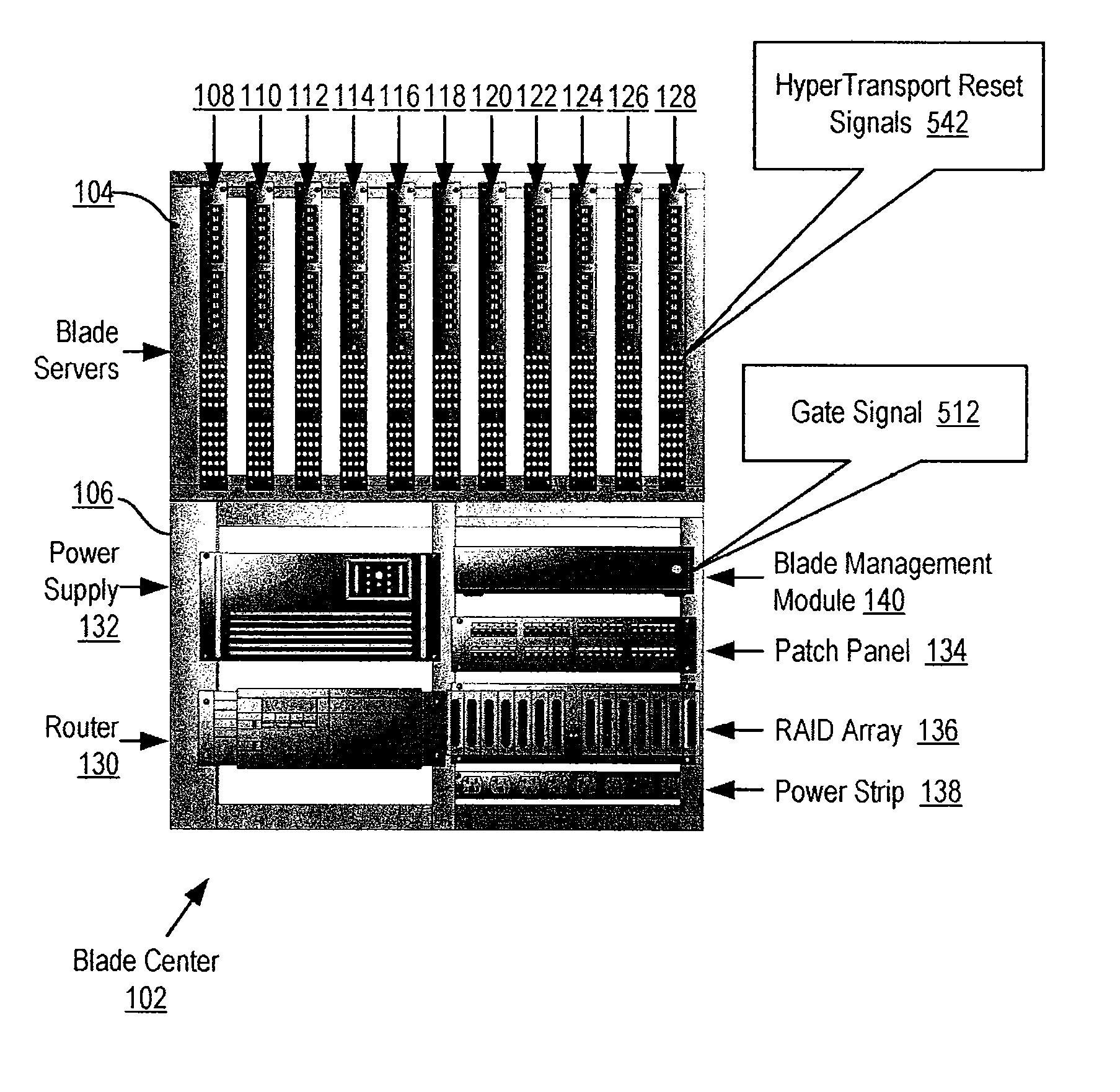
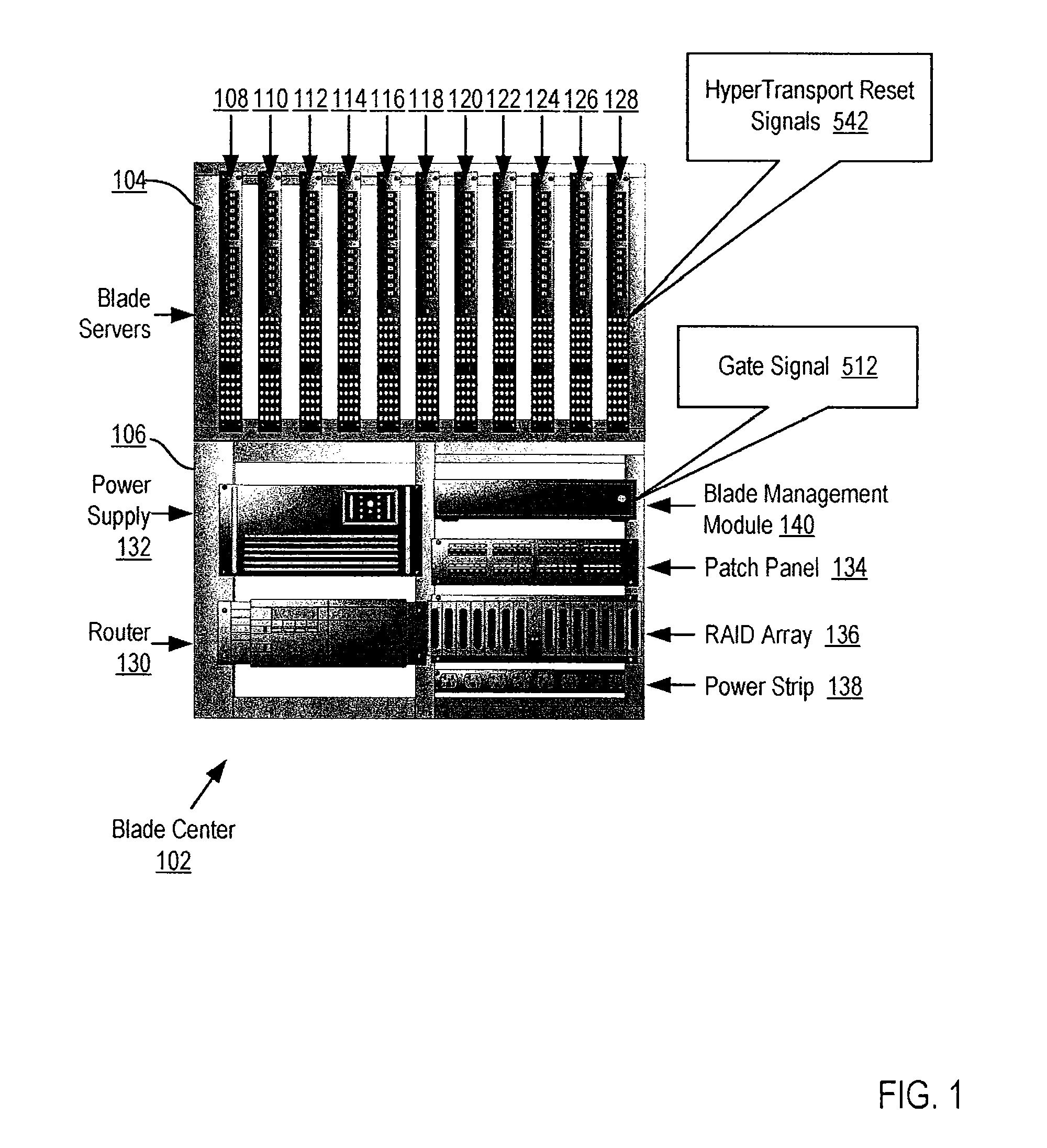
[0016]Exemplary methods, systems, and products for resetting a HyperTransport™ link in a blade server according to embodiments of the present invention are described with reference to the accompanying drawings, beginning with FIG. 1. FIG. 1 sets forth a front view of an exemplary blade center (102) that is configured for resetting a HyperTransport link in a blade server according to embodiments of the present invention. The system of FIG. 1 includes eleven blade servers (108-128) implemented in blade form factor and installed in a cabinet bay (104) of a blade center (102). Each blade server includes a reset sync module, a baseboard management controller and a blade processor that employs HyperTransport technology. The reset sync module may be a state machine implemented using a programmable logic device, a programmable logic controller, logic gates and flip flops, relays and the like, or the reset sync module may be a module of computer program instructions that cause the baseboard ...


PUM


Abstract

A design structure embodied in a machine readable storage medium for designing, manufacturing, and / or testing a design is described for resetting a HyperTransport link in a blade server, including reassigning, by a blade management module, a gate signal from enabling a transceiver to signaling a HyperTransport link reset; sending, by the blade management module to a reset sync module on an out-of-band bus, the gate signal; and in response to the gate signal, sending, by the reset sync module to the blade processor, HyperTransport reset signals. The HyperTransport link includes a bidirectional, serial / parallel, high-bandwidth, low-latency, point to point data communications link. The blade server includes the blade processor, the reset sync module, and the baseboard management controller. The blade server is installed in the blade center. The blade center includes the blade management module. The blade management module is coupled to the baseboard management controller by the blade communication bus.

Description

CROSS-REFERENCE TO RELATED APPLICATION[0001]This application is a continuation-in-part of co-pending U.S. patent application Ser. No. 11 / 748,177, filed May 14, 2007, which is herein incorporated by reference.BACKGROUND OF THE INVENTION[0002]1. Field of the Invention[0003]The field of the invention is generally related to design structures, and more specifically, design structures for resetting a HyperTransport link in a blade server.[0004]2. Description of Related Art[0005]The development of the EDVAC computer system of 1948 is often cited as the beginning of the computer era. Since that time, computer systems have evolved into extremely complicated devices. Today's computers are much more sophisticated than early systems such as the EDVAC. Computer systems typically include a combination of hardware and software components, application programs, operating systems, processors, buses, memory, input / output devices, and so on. As advances in semiconductor processing and computer archit...

Claims


Application Information

Patent Timeline
Patent Type & Authority Applications(United States)
IPC IPC(8): G06F15/16
CPCG06F13/409H04L41/24
Inventor BANDHOLZ, JUSTIN P.HEINZMANN, ANDREW S.PARSONESE, JAMES J.
Owner IBM CORP
Learn More