High pressure safety valve, system and method

a safety valve and high-pressure technology, applied in the field of safety valves, can solve the problems of high cost of equipment used to compress or transfer gases to the tank, damage to property within the vicinity of the tank, and inability to rupture discs, etc., and achieve the effect of reducing gas leakage and reducing gas leakag

Inactive Publication Date: 2008-11-27
MASINGALE LEVI D
View PDF20 Cites 16 Cited by
  • Summary
  • Abstract
  • Description
  • Claims
  • Application Information

AI Technical Summary

Benefits of technology

[0017]In yet another embodiment, the present invention comprises a method for substantially reducing gas leakage from an over-pressurized tank filled with pressurized content. In still another embodiment, the present invention is a system for providing substantially reducing gas leakage from an over-pressurized tank filled with pressurized content.

Problems solved by technology

However, it is also known in the art that a sudden release of compressed gas or fluid from the cylinder, such as may occur during the rupture of the valve on a high pressure tank, may be extremely hazardous to those people or damaging to property within the vicinity of the tank.
Moreover, the location of the primary rupture disc in the inlet / outlet port 101 presents problems when the valve is sheared from the tank, thereby making the rupture disc useless.
Equipment that is used to compress or transfer gases to a tank is expensive, and it is a common practice to compress and transfer the gas at a central location and thereafter, transport the compressed gas within the high-pressure tanks or cylinders.
These cylinders can be as destructive as a missile should they rupture because of the high pressure at which these tanks are maintained.
Such openings in the tank are of a predetermined, smaller width, and are female threaded to permit the connection of a closure valve or shutoff valve 100 either of which are exceedingly rugged in their construction, but nevertheless are weaker than the tank structure itself.
If the tanks are accidentally dropped or the valve structures on the tank or otherwise hit or sheared off (e.g., due to a lateral impact), the valve body may externally shear from the cylinder upon which it is mounted.
However, such compressed gas cylinders are required by law to be fitted with a relief device which are adapted to relieve pressure from the compressed gas cylinders in the event of an over-pressurized cylinder or other extreme danger (e.g., a fire event—as used herein, the term “over-pressurization event” refers to any event which would cause the contents stored in a tank to suddenly be released in an uncontrolled fashion).
However, the vast majority of relief devices are displaced within the inlet / outlet valve at a point outside (or, exterior to) the cylinder.
In such situations, the relief devices are prone to being sheared off (or away from) the compressed gas cylinder (such as may happen during the cylinder unexpectedly falling from a truck onto a hard surface, for example).
When the relief devices are sheared off of the compressed gas cylinder, the compressed gas is likely to rapidly escape from the cylinder because now, there is an uncontrolled opening in the cylinder.
In most instances, the rapid release of compressed gas is an extreme danger to anyone in range of the compressed gas cylinder because the gas cylinder can now act as a potential missile or similar projectile.
In some situations, the surrounding buildings and equipment are also prone to damage, thereby exacerbating the danger potential.
Additionally, if the gas is flammable, a rapid release of flammable gas may result in a severe explosion.
This disclosures deficient because it requires a modification of existing valves.
This disclosure is also deficient because it does not provide any internal relief disk truly prescient he cylinder reaches extremely high pressures.
This disclosure, too, suffers in that it requires a complete modification of existing safety valve systems.
Moreover, this disclosure is not capable of resetting itself, so that the entire (broken) gas cylinder must be repaired at the next available time.
This delay leads to loss of income, as well as lost time and resources.
Moreover, this disclosure cannot reset itself after a shear event, and while this disclosure may prevent rapid decompression of the gas cylinder, when a shear event occurs, the entire valve must thereafter be replaced.
Moreover, this disclosure has no internal relief device.
Again, while this device is used for over pressure of pressurized gas cylinders, it too suffers because it has no internal relief device president.

Method used


Image

  • High pressure safety valve, system and method
  • High pressure safety valve, system and method
  • High pressure safety valve, system and method

Examples


Embodiment Construction

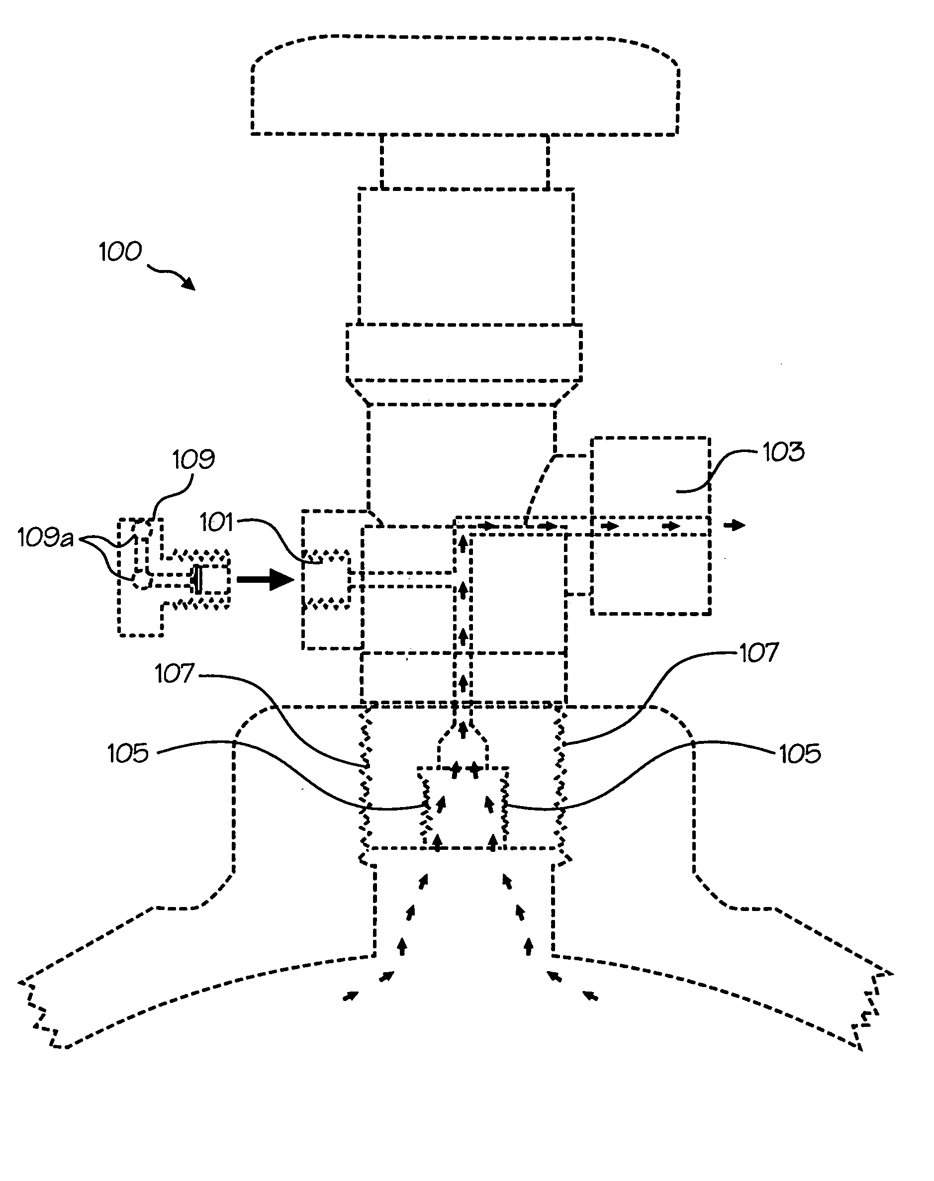
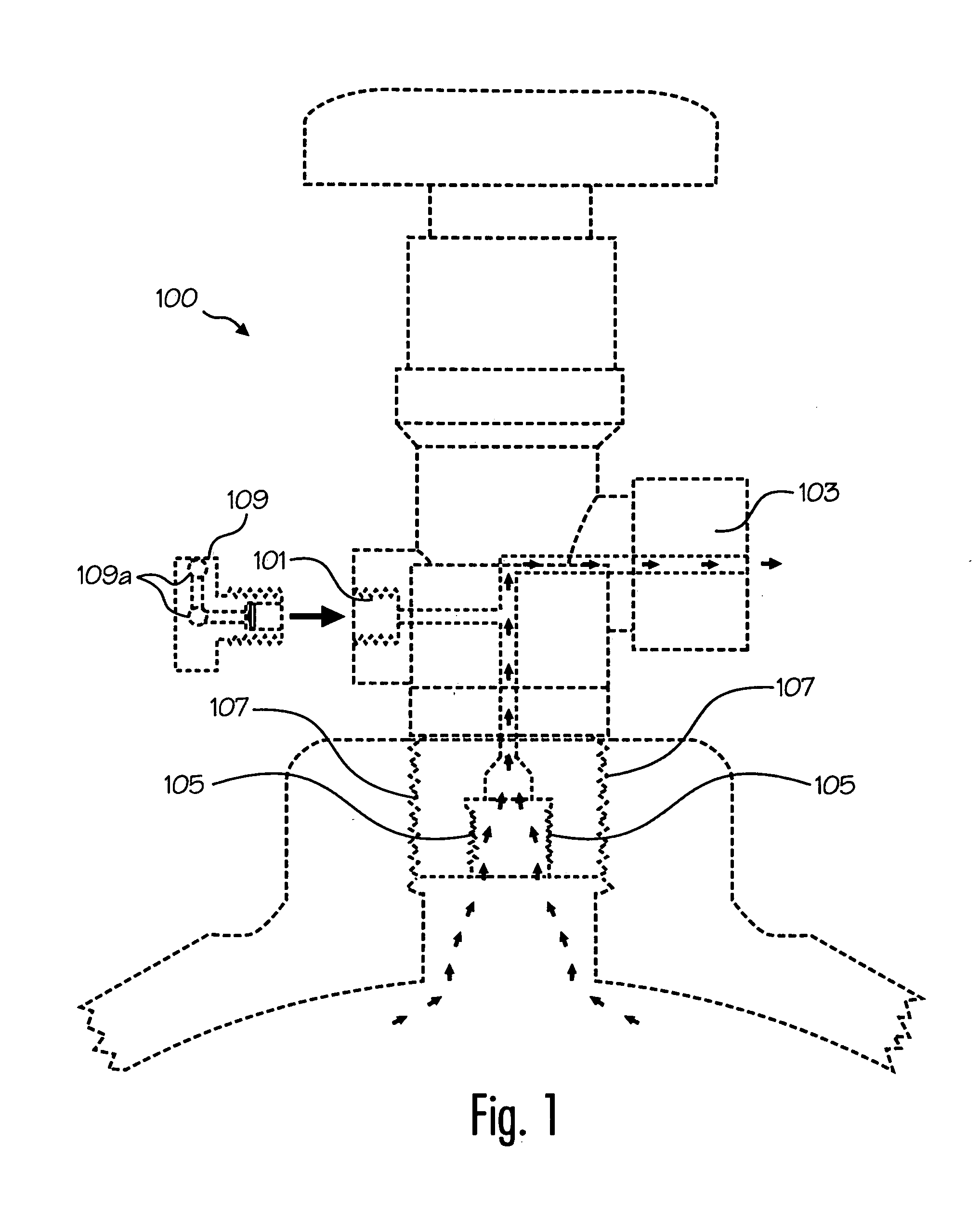
[0039]The present invention is a high pressure, compression safety valve apparatus, system and method which is adapted for internal mechanical coupling to a valve typically used with or on a conventional compressed gas cylinder, tank or container, and which does not require any modification to existing inlet / outlet valves found on conventional compressed gas cylinder tanks.

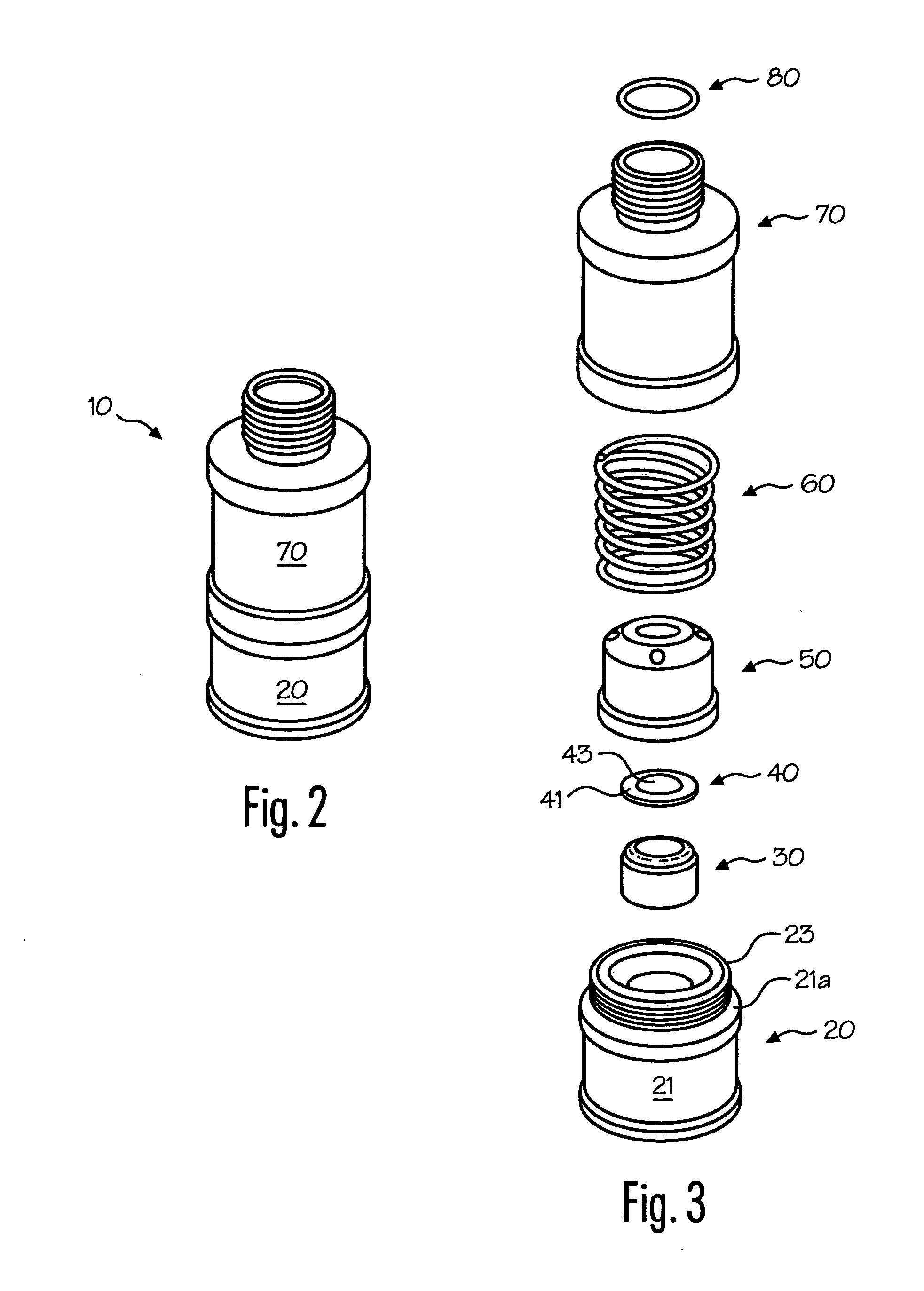
[0040]FIGS. 2 and 4 illustrate an example of the present invention as a single apparatus 10 for internal mechanical coupling to a conventional compressed content tank valve 100 through the valve's female threads 105 (as seen generally in FIG. 15D). As seen in FIGS. 2-6, the safety valve 10 of the present invention comprises, in one embodiment, a housing base 20, a rupture disc holding means 30, at least one rupture disk 40, a piston 50, a spring 60, an outer housing cylinder 70, and an optional sealing means 80.

[0041]As seen in FIGS. 3 and 8, housing base 20 is a single housing apparatus of general cylindrical sha...


PUM


Abstract

The present invention comprises, in one embodiment, a compression safety valve apparatus adapted to engagingly connect to an existing gas cylinder valve. In one embodiment, the present invention comprises a housing base having a first bore, a rupture disc holding means having a second bore, at least one rupture disk, a piston having at least a third bore, a spring, and an outer housing cylinder having a forth bore, the first bore, the second bore and the third bore all being in gas flow communication with the compressed content of the tank. In operation, for example, during an over-pressurization event occurs, the extreme force of the escaping gas places a force on the bottom surface of the present invention's rupture disc assembly, so that the piston's beveled surface substantially mechanically engages the outer housing's upper ceiling. This mechanical engagement allows gas to continue to escape from the tank through one or more bleeder bores and a gap.

Description

PRIORITY CLAIM[0001]The present invention claims priority from U.S. Provisional Patent Application No. 60 / 931,561, filed May 24, 2007 and entitled “High Pressure Safety Valve”.FIELD OF INVENTION[0002]The present invention relates generally to safety valves used in conjunction with pressurized gas or fluid cylinders, tanks or like units, wherein such safety valves are designed to substantially reduce or shut off the flow of compressed content from the cylinder when rapid release of the compressed content within the cylinder occurs.BACKGROUND OF THE INVENTION[0003]It is well known in the art that pressurized gas or fluid is capable of performing tremendous amount of work. However, it is also known in the art that a sudden release of compressed gas or fluid from the cylinder, such as may occur during the rupture of the valve on a high pressure tank, may be extremely hazardous to those people or damaging to property within the vicinity of the tank.[0004]FIG. 1 illustrates a typical prio...

Claims


Application Information

Patent Timeline
Patent Type & Authority Applications(United States)
IPC IPC(8): F16K17/00
CPCF16K1/307F16K17/30F17C13/04Y02E60/321F17C2201/0104F17C2205/0314F17C2205/0329F17C2205/0332F17C2205/0338F17C2205/0382F17C2205/0394F17C2221/011F17C2221/012F17C2221/014F17C2221/017F17C2221/033F17C2223/0123F17C2223/036F17C2260/036Y02E60/32Y10T137/7728
Inventor MASINGALE, LEVI D.
Owner MASINGALE LEVI D
Why Eureka
Try Eureka