Cooling module

a technology of cooling module and cooling module, which is applied in the direction of machines/engines, combustion air/fuel air treatment, transportation and packaging, etc., can solve the problems of increasing difficulty in providing sufficient free space above the front end panel, so as to reduce the weight of the cooling module, reduce the effect of increasing the temperature of the air to be introduced into the engine and effectively us

Inactive Publication Date: 2008-11-27
DENSO CORP +2
View PDF4 Cites 17 Cited by
  • Summary
  • Abstract
  • Description
  • Claims
  • Application Information

AI Technical Summary

Benefits of technology

[0011]Accordingly, the air cleaner unit is configured such that a part of the air cleaner unit serves as a part of the air introducing portion of the fan shroud. In other words, the air cleaner unit and the air introducing portion of the fan shroud share a wall between them. Therefore, the weight of the cooling module is reduced. Since the heat exchanger and the air cleaner unit are arranged in the horizontal direction, a space provided above the cooling module in a condition mounted in an engine compartment of the vehicle is increased. For example, the space is effectively used for a pedestrian protection system.
[0012]In addition, since the front end wall of the air cleaner unit is offset from the heat exchanger, when viewed along the flow of the air, that is, from the front side, the air cleaner unit is cooled by air that has not passed through the heat exchanger. As such, an increase in temperature of the air to be introduced into the engine is reduced. Further, since the clearance is provided between the side wall of the air cleaner unit and the heat exchanger, air is conducted from an upstream position of the heat exchanger toward a downstream position of the heat exchanger through the clearance. Therefore, the air cleaner unit is effectively cooled by the air passing through the clearance. As such, engine torque is increased while restricting the increase in temperature of the air to be introduced into the engine.
[0013]Accordingly, the cooling module having the structure capable of reducing the weight and increasing the space on its top in the condition mounted in the engine compartment while effectively cooling the air to be introduced into the engine is provided.

Problems solved by technology

Further, the weight of the cooling module increases.
Also, since the air cleaner is disposed at the upper beam portion of the fan shroud, it will be difficult to sufficiently provide the free space above the front end panel.

Method used


Image

  • Cooling module
  • Cooling module
  • Cooling module

Examples


first embodiment

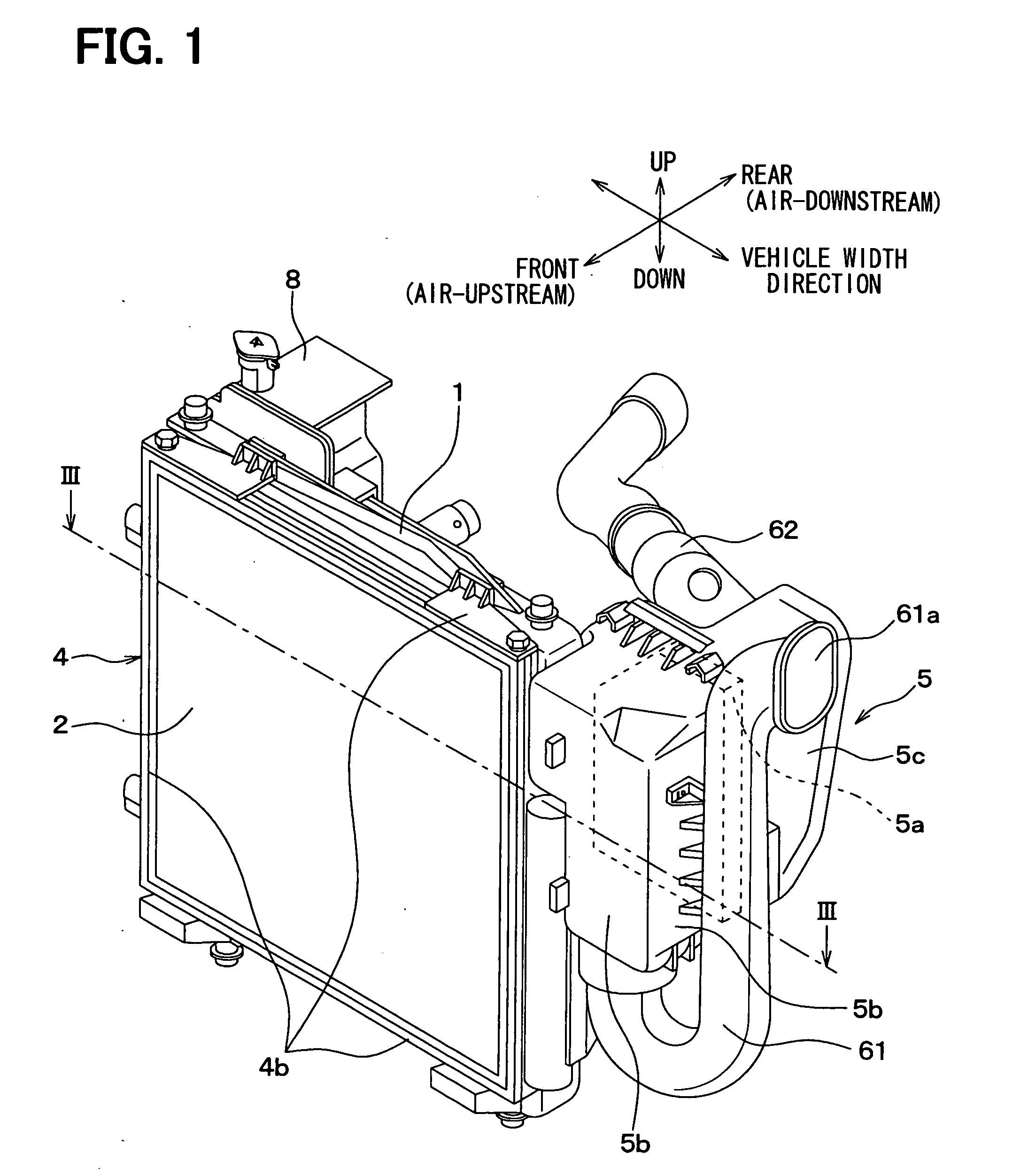
[0021]A first embodiment of the present invention will now be described with reference to FIGS. 1 to 5. In the present embodiment, a cooling module is mounted in an engine compartment provided at a front end of a vehicle.

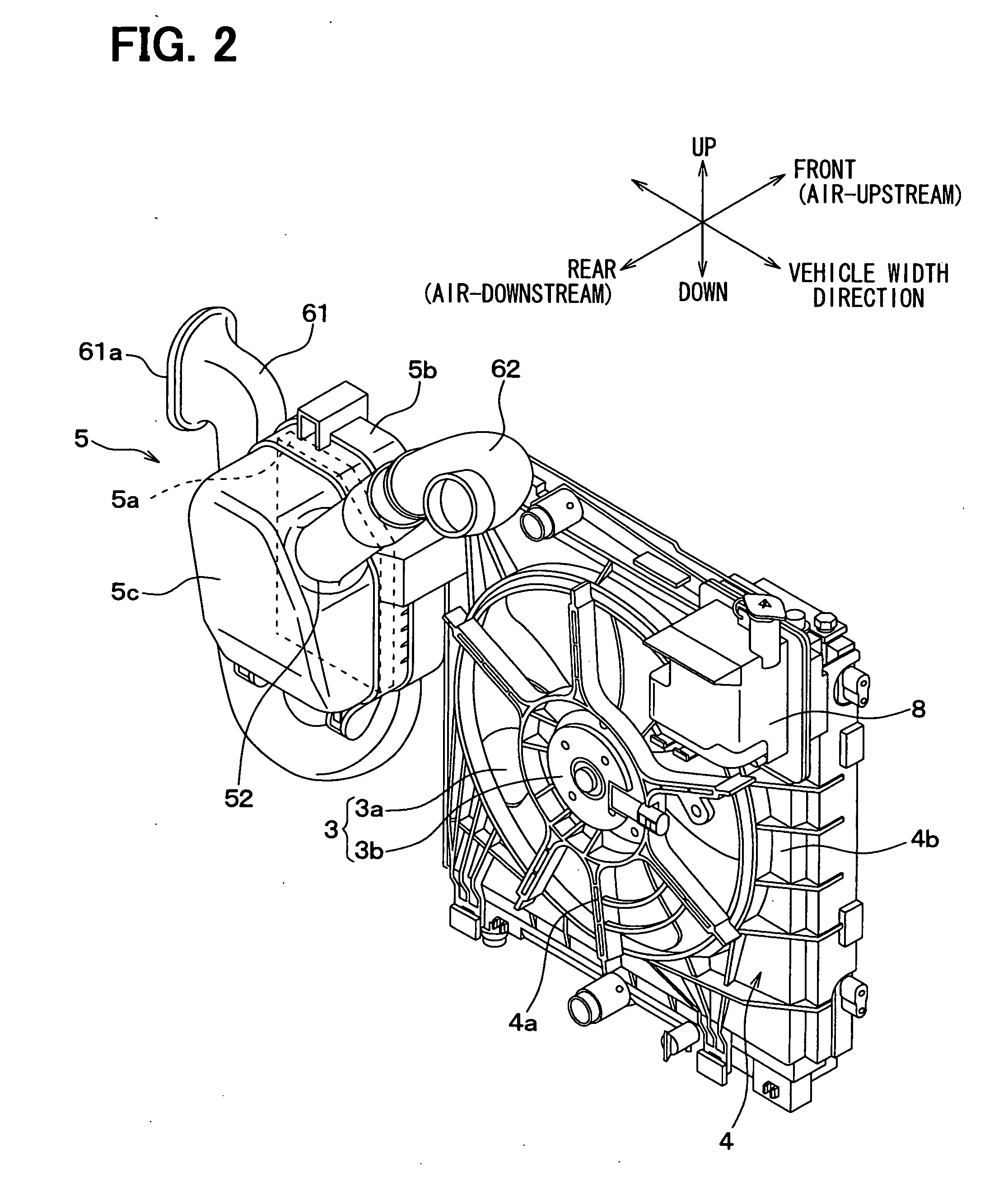
[0022]Referring to FIGS. 1 to 3, the cooling module generally includes a radiator 1, a condenser 2, an electric fan unit (blower) 3, a fan shroud 4 and an air cleaner unit 5. The radiator 1 is a heat exchanger that performs heat exchange between a cooling fluid of an internal combustion engine (hereinafter, engine) and outside air introduced from an outside of a vehicle, thereby cooling the cooling fluid. The condenser 2 is a heat exchanger that performs heat exchange between a refrigerant of a refrigerant cycle of a vehicular air conditioner (not shown) and the outside air, thereby cooling the refrigerant.

[0023]The blower 3 is disposed to introduce the outside air to the radiator 1 and the condenser 2 for cooling the radiator 1 and the condenser 2. The fan shroud 4...

second embodiment

[0055]A second embodiment of the present invention will now be described with reference to FIG. 6. Hereinafter, like components are denoted by like reference characters and a description thereof is not repeated. In FIG. 6, the illustration of the reserve tank 8 is omitted.

[0056]In the present embodiment, as shown in FIG. 6, the radiator 1 is fixed to the fan shroud 4. The fan shroud 4 to which the radiator 1 is fixed is mounted to the vehicle body 10 through the elastic rubber bushings 9. For example, the fan shroud 4 has pins 4c on its upper and lower ends. The rubber bushings 9 are fixed to the pines 4c beforehand. The pins 4c are engaged with portions of the vehicle body 10. Thus, the fan shroud 4 to which the radiator 1 is fixed, that is, the cooling module is mounted to the vehicle. In this case, the condenser 2 can be fixed to the radiator 1 beforehand. Alternatively, the condenser 2 can be independently and directly fixed to the vehicle body 10. Also in the present embodiment...


PUM


Abstract

A cooling module includes a heat exchanger, a blower, a fan shroud and an air cleaner unit for filtering air to be introduced into an engine of a vehicle. The fan shroud holds the blower on a downstream side of the heat exchanger with respect to a flow of air passing through the heat exchanger and has an air introducing portion defining an air passage from the heat exchanger to the blower. A front end of the air cleaner unit is offset from the heat exchanger with respect to a horizontal direction. A side wall of the air cleaner unit partly forms the air introducing portion. A clearance is provided between the side wall and the heat exchanger such that air upstream of the heat exchanger is conducted toward a position downstream of the heat exchanger through the clearance.

Description

CROSS REFERENCE TO RELATED APPLICATION[0001]This application is based on Japanese Patent Application No. 2007-136603 filed on May 23, 2007, the disclosure of which is incorporated herein by reference.FIELD OF THE INVENTION[0002]The present invention relates to a cooling module including a fan shroud and an air cleaner unit.BACKGROUND OF THE INVENTION[0003]For example, heat exchangers, such as a radiator and a condenser, and a blower for introducing air to the heat exchangers are mounted to a vehicle body through a front end panel. The front end panel is also known as a shroud panel, a carrier, a radiator support and the like. The front end panel is integrally formed with a fan shroud of the blower. The fan shroud is configured to support a fan of the blower and to form an air passage from the heat exchangers to the fan.[0004]Japanese Unexamined Patent Application Publication No. 11-171041 describes a cooling module having a front end panel. In the described cooling module, the front...

Claims


Application Information

Patent Timeline
Patent Type & Authority Applications(United States)
IPC IPC(8): F01N5/02
CPCB60K11/04B60K13/02F02M35/06F02M35/161
Inventor SASANO, NORIHISAMAEDA, AKIHIRONAKAWATASE, AKIRAKANZAKA, RYUJIMATSUBARA, YUJIKIMURA, SHINGOENOMOTO, AKIRATANAKA, KAZUYASUZUKI, KOUJI
Owner DENSO CORP
Why Eureka
Try Eureka