Supercharge Your Innovation With Domain-Expert AI Agents!

Method of controlling a screwdriving power tool

a power tool and power tool technology, applied in the direction of drilling machines and methods, metal working apparatus, drilling accessories, etc., can solve the problems of not being suitable for thread-forming applications, not being suitable for hand-held screwdriving power tools, and not being suitable for known methods. to achieve the effect of stable screw connection

Inactive Publication Date: 2008-11-27
HILTI AG
View PDF14 Cites 38 Cited by
  • Summary
  • Abstract
  • Description
  • Claims
  • Application Information

AI Technical Summary

Benefits of technology

The present invention provides a control method for a hand-held screwdriving power tool that overcomes the disadvantages of previous methods. The method uses an operational torque to control the screwdriving process, regardless of the material characteristics of the construction component. The maximum tightening value of the operational torque is determined based on the curve of the operational torque until a reference point is reached. The reference point is defined as the point in time at which the triggering screw-in depth is reached plus a predetermined time period. The speed of the screwdriving process is reduced after the reference point to ensure a stable screw connection. The control method uses a contact sensor to detect the triggering screw-in depth, and the sensor is placed in the tool holder to ensure reliable detection. The sensor can be a contact sleeve or a sensor connected to the control device. The invention provides a more accurate and efficient method for controlling a hand-held screwdriving power tool.

Problems solved by technology

The known method is disadvantageous in that it is only suitable for applications which stay the same, particularly because of the depth sensor that is provided and because of the necessity of predetermined shut-off screwdriving torques.
On the other hand, the method is not suitable for applications in which several screwdriving processes follow one another directly at diverging angles between a work axis and a surface of the constructional component or in which the material characteristics of the respective constructional component are different.
Consequently, the known method is not suitable for use in hand-held screwdriving power tools.
In particular, it is not suitable for thread-forming applications in which the fastening elements are not screwed into previously prepared holders but in which, rather, the holders are only formed when the fastening elements are screwed into the respective constructional component by cutting or displacement.

Method used


Image

  • Method of controlling a screwdriving power tool
  • Method of controlling a screwdriving power tool
  • Method of controlling a screwdriving power tool

Examples


Embodiment Construction

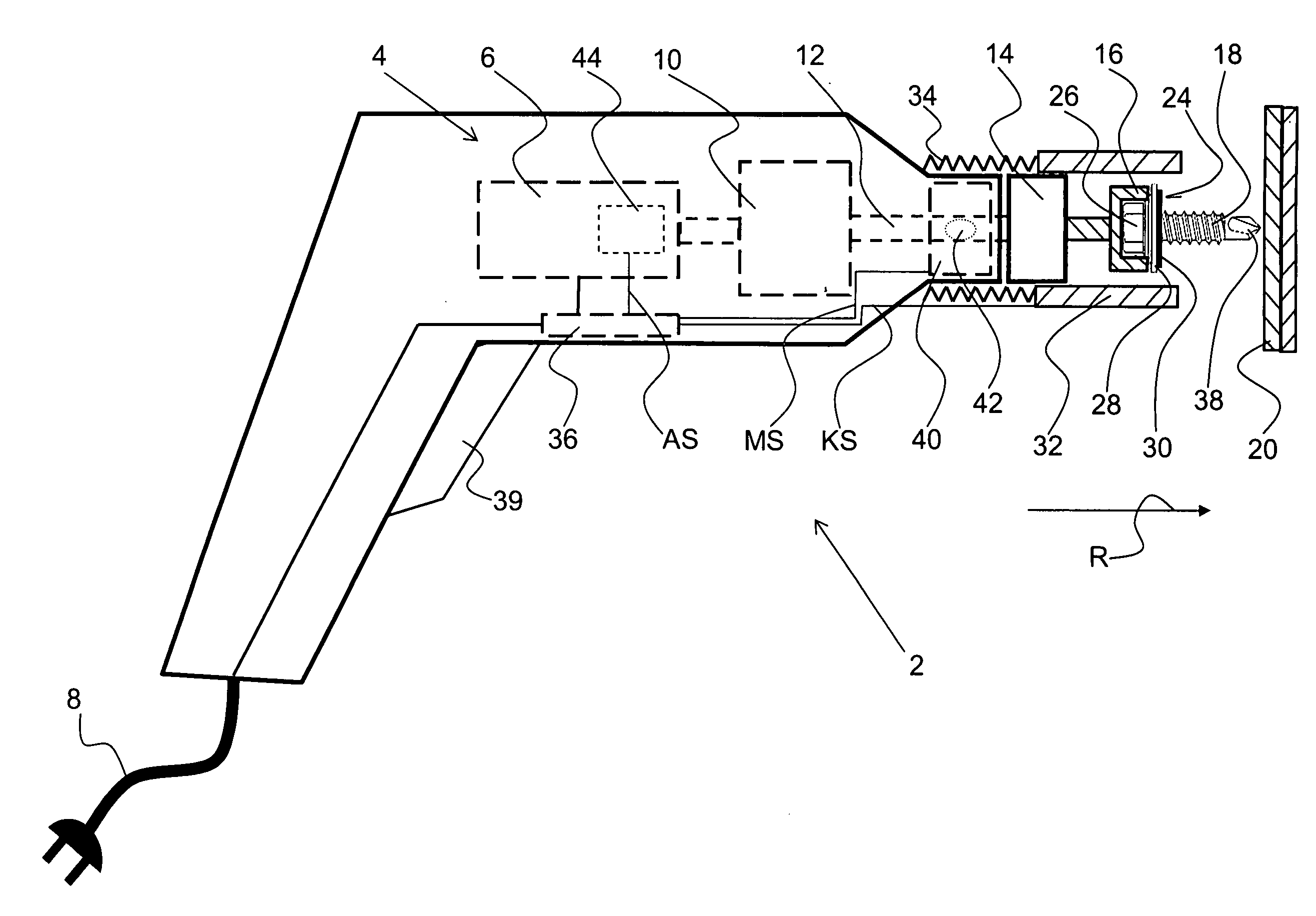
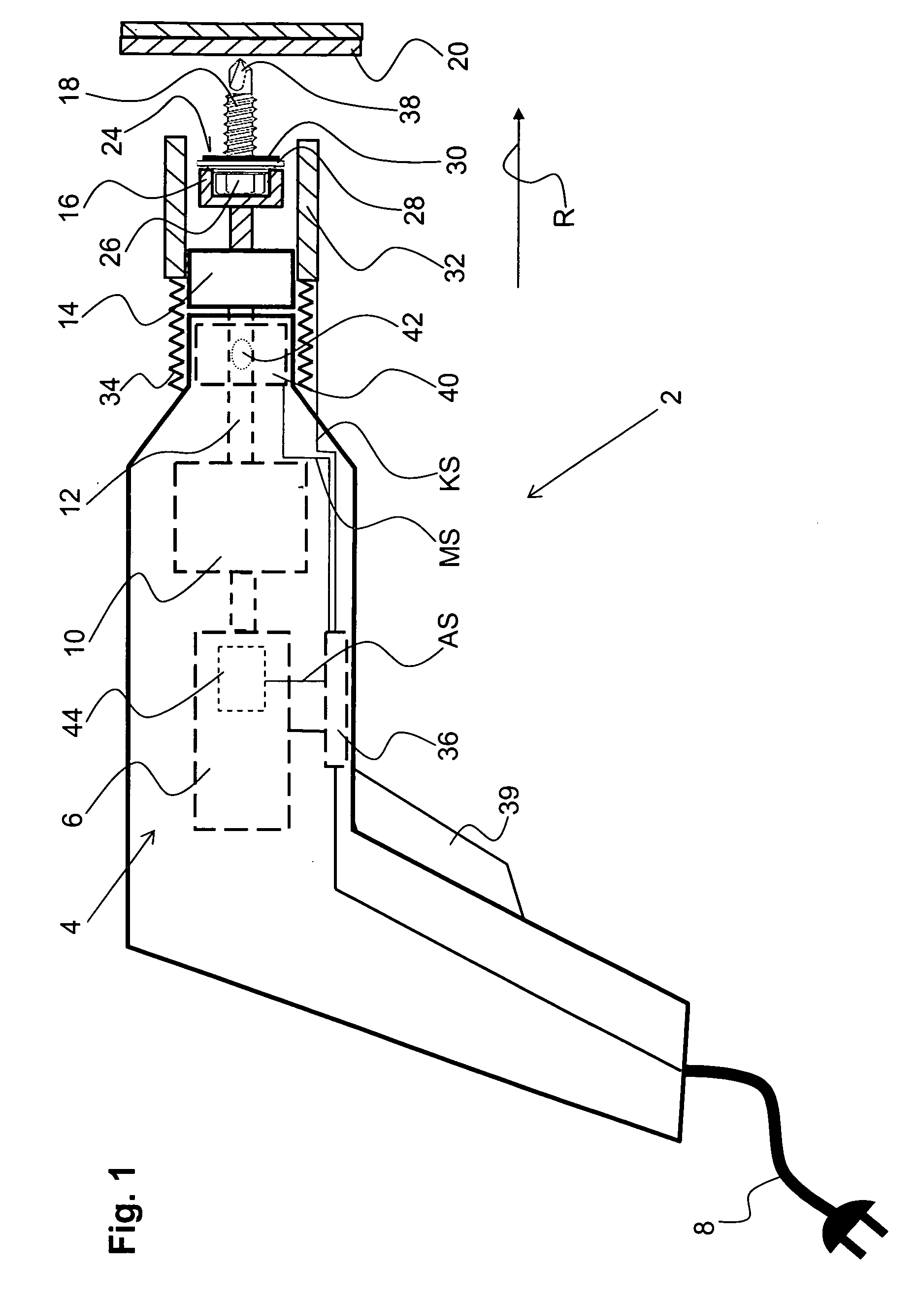
[0028]FIG. 1 shows an electrically operated screwdriving power tool 2 in the form of a hand-held drywall screwdriving power tool. This screwdriving power tool 2 has a drive 4 with a motor 6, e.g., a brushless motor, which, as is shown, is supplied with power by a line voltage cable 8 or, alternatively, a battery pack, and a gear unit 10.

[0029]A drive shaft 12 which is connected to a working tool holder 14 in the form of a bit holder is driven by the drive 4. A screw bit 16 is inserted into this tool holder 14, and a fastening element 18 such as, e.g., a self-tapping screw, can be screwed into a constructional component 20 along a screw-in direction R by means of the screw bit 16. The constructional component 20 can be formed of one part or, as is shown, of multiple parts, e.g., in the form of a sheet to be fastened to a support member.

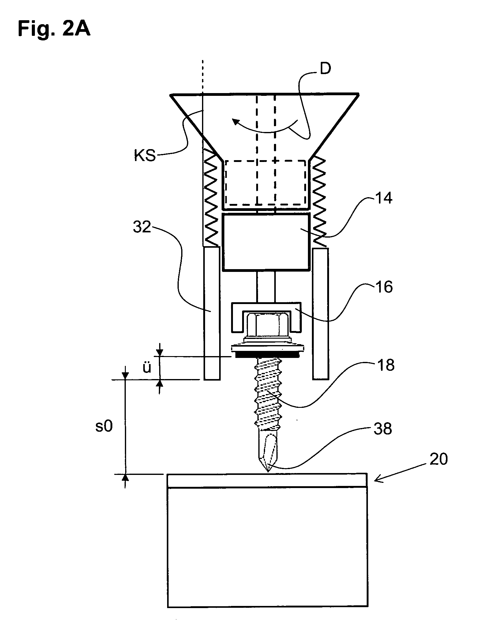
[0030]The fastening element 18 has a contact area 24 which is formed in the shown embodiment by a side of a flexible ring 30 facing in the screw-in di...


PUM


Abstract

In a method for controlling a drive (4) of an electrically operated screwdriving power tool (2) during a screwdriving process, a tool holder (14) with a screw bit (16) fastened thereto is acted upon by the drive (4) to drive a fastening element (18) having a contact area (24) into a constructional component (20), with the screw bit movable up to a maximum screw-in value (Dmax) at a speed (D) and a operational torque (MA) generated between the screw bit (16) and the fastening element (18), and after it has been detected that a predetermined triggering screw-in depth (s0) has been reached, the speed (D) is reduced from the maximum screw-in value (Dmax) during a tightening process (AV), and, when it has been detected that a determined end value of the operational torque (MA) is reached, the screwdriving process is terminated.

Description

BACKGROUND OF THE INVENTION[0001]1. Field of the Invention[0002]The invention relates to a method of controlling a screwdriving process carried out with a line voltage-operated or battery-operated screwdriving power tool, particularly a hand-held screwdriving power tool, and to a hand-operated screwdriving power tool with a control device for carrying out the method. During a screw-in process, a tool holder with a screw bit fastened therein is acted upon by the drive in order to screw a fastening element having a contact area into a constructional component. The screw bit is moved at a maximum screw-in speed and generates an operational torque with respect to the fastening element. When it is detected that a predetermined triggering screw-in depth is reached shortly before the contact area of the fastening element contacts the constructional component, the speed is reduced from the maximum screw-in value in the course of a tightening process. When it has been detected that a determi...

Claims


Application Information

Patent Timeline
Patent Type & Authority Applications(United States)
IPC IPC(8): B25B21/00B23Q5/00
CPCB25B21/00B25B23/0064B25B23/147
Inventor HRICKO, PETERJOHN, ALEXANDERBOENI, HANSSCHMIDT, PEERKUNTNER, JOCHEN
Owner HILTI AG
Features
  • R&D
  • Intellectual Property
  • Life Sciences
  • Materials
  • Tech Scout
  • Unparalleled Data Quality
  • Higher Quality Content
  • 60% Fewer Hallucinations
Learn More