Braced sound barrier vacuum panel

a vacuum panel and sound barrier technology, applied in the field of braced sound barrier vacuum panel, can solve the problems of only moderate sound attenuation efficiency, fragile and expensive panels, and underconsiderable compression of panels, so as to avoid inward flexing and prevent the effect of upper and lower sheets

Inactive Publication Date: 2008-11-27
RICKARDS MICHAEL JOHN
View PDF14 Cites 23 Cited by
  • Summary
  • Abstract
  • Description
  • Claims
  • Application Information

AI Technical Summary

Benefits of technology

[0007]According to the present invention the inward flexing of the upper and lower sheets is largely prevented by the use of bracing strips placed outside the vacuum panel, FIGS. 2a and 2b, or inside, FIGS. 3a and 3b or outside on one sheet and inside on the other. The internal bracing strips may also be interlaced, FIGS. 4a, 4 and 4c. In all these designs the upper and lower sheets remain substantially flat thus avoiding the inward flexing of the upper (1) and lower (2) sheets shown in FIG. 1 and so making a much narrower and consequently thinner peripheral wall possible. The rejection of sound by the panel is controlled principally by the thickness of the peripheral wall according to the empirical equation:Rejectionlevel(dB)=20log[UppersheetareaPerimeterwallcrosssectionalarea]
[0008]It is important to realise that the sound is not attenuated by the vacuum panel. The sound wave arriving at the upper sheet, for example, finds nowhere to go and is reflected back towards the source. Because the fraction of transmitted sound, through the thin peripheral wall and the residual air in the panel, is so very small the sound rejection level is substantially independent of its frequency. This unique property of vacuum panels is something new in the field of acoustics and made all the more remarkable by the fact that the panels can be made from readily available, inexpensive materials and the design is well suited to automated production.The principal advantages of braced vacuum panels are:
[0009]1. They achieve a very high level of sound rejection maintained over a wide range of frequencies from 100 Hz to over 3000 Hz and they provide excellent thermal insulation.
[0010]2. They are robust in use and have flat surfaces, easily fixed to battens and masonry, they are light in weight and capable of maintaining vacuum integrity over long periods of time, at least ten years.
[0011]3. They can be inexpensively mass produced, in a variety of shapes and sizes, from readily available raw materials.

Problems solved by technology

The problems arise from two main sources, the considerable compression a panel is under because of atmospheric pressure and the inevitable passage of heat and sound through whatever structure is used to separate the upper and lower sheets of the panel.
The use of rigid structures inside vacuum insulating panel, VIP, such as micro porous silica or rigid polyurethane foam, to overcome the effect of atmospheric compression has met with considerable commercial success despite the resulting panels being fragile and expensive to manufacture.
However, such ‘filled’ panels have a high resistance to the passage of heat and represent a major advance in thermal insulation though their sound attenuating efficiency is only moderate compared with materials specifically developed for sound dampening applications.

Method used


Image

  • Braced sound barrier vacuum panel
  • Braced sound barrier vacuum panel
  • Braced sound barrier vacuum panel

Examples


example 1

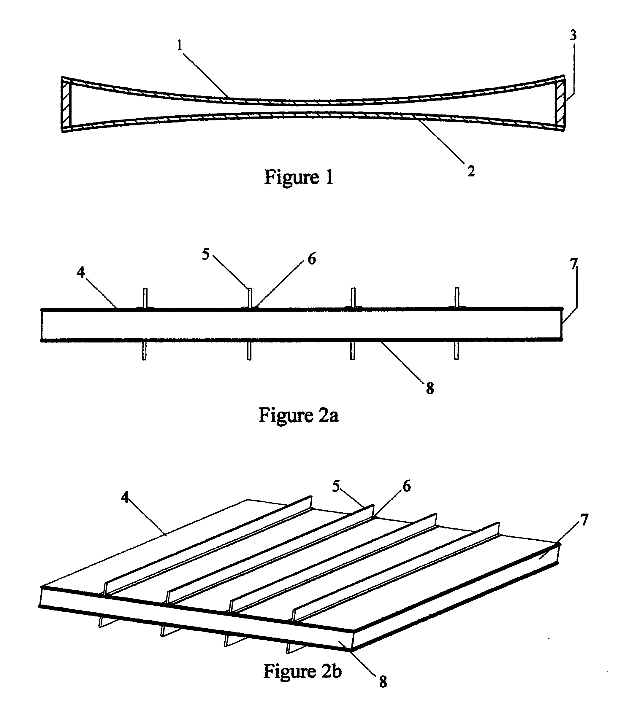
[0021]A square vacuum panel, illustrated in FIGS. 2a and 2b, with upper (4) and lower (8) sheets made from 0.8 mm thick mild steel and having 400 mm sides separated by a 15 mm high peripheral wall (7) made from 0.22 mm thick mild steel.

[0022]The upper (4) and lower (8) sheets were externally braced with four mild steel strips (5) 15 mm high and 0.8 mm thick having 5 mm wide fixing flanges (6). All components were assembled with epoxy resin and the enclosed space evacuated to less than 100 Pa. Placing the bracing strips externally to the panel brings them under compression by the action of atmospheric pressure on the panel.

[0023]This panel gave a sound rejection level in excess of 45 dB at both 100 Hz and 900 Hz.

example 2

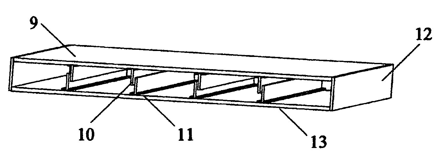
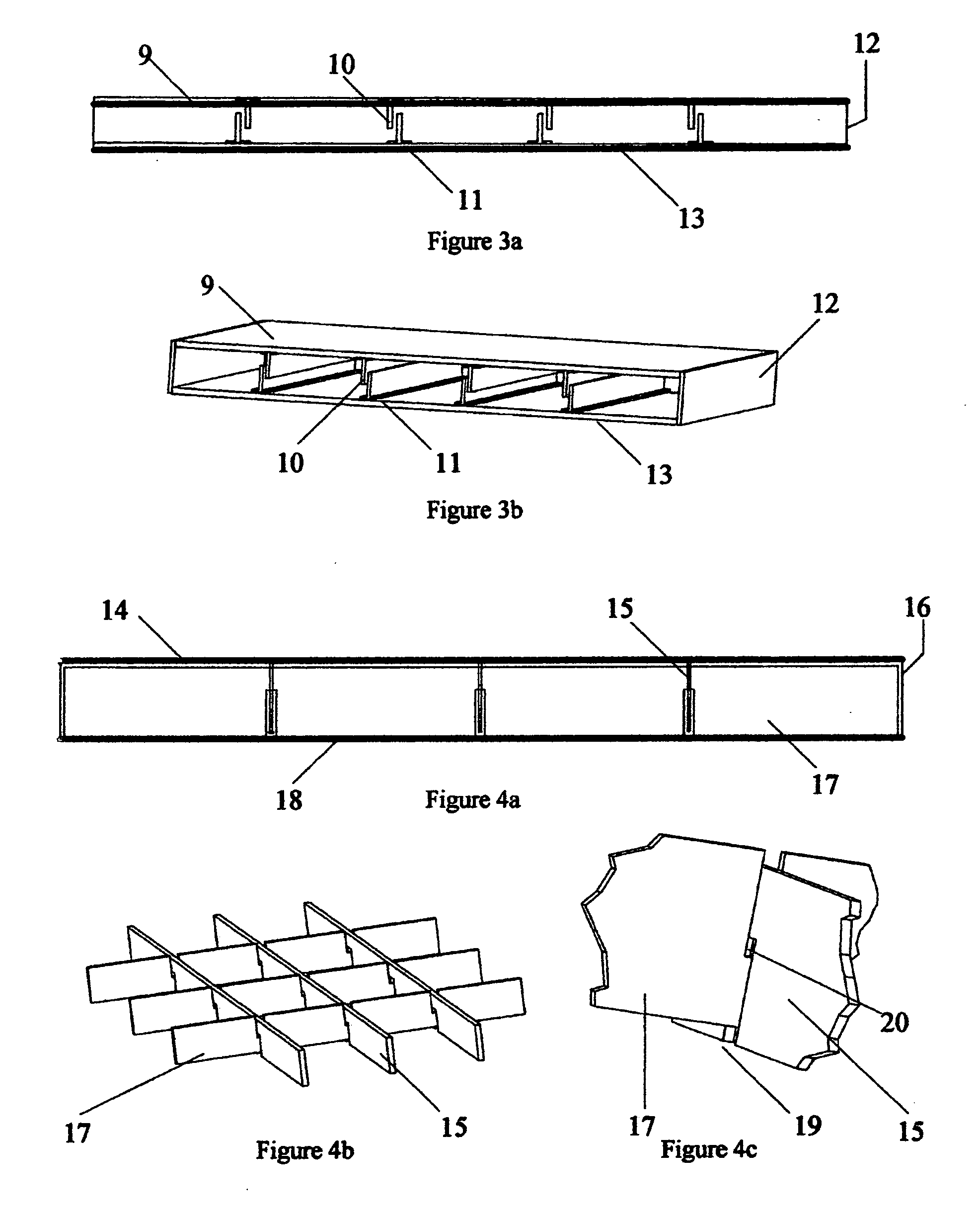
[0024]A square vacuum panel, illustrated in FIGS. 3a and 3b, with upper (9) and lower (13) sheets made from 0.8 mm thick mild steel and having 400 mm sides separated by a 20 mm high peripheral wall (12) made from 0.22 mm thick mild steel.

[0025]The sheets were internally braced with four strips (10) on each sheet the strips being 390 mm long and 15 mm high made from 0.8 mm thick mild steel with 5 mm wide fixing flanges (1). All components were assembled with epoxy resin and the enclosed space evacuated to less than 100 Pa. Placing the bracing strips inside the panel brings them under tension by the action of atmospheric pressure on the panel.

The sound rejection level for this panel was found to be more than 40 dB at 100 Hz and 900 Hz.

example 3

[0026]A square vacuum panel, as illustrated in FIGS. 4a, 4b and 4c, with upper (14) and lower (18) sheets made from glass fibre reinforced polyester resin 4 mm thick having a glass content of 2.4 kg m−2. The sheets having 400 mm sides and separated by a peripheral wall (16) 20 mm high and 1.5 mm thick made from glass fibre reinforced polyester resin having a glass content of 900 g m−2.

[0027]The upper (14) and lower (18) sheets were braced internally with three interlaced strips (15) 1.5 mm thick and 15 mm high made in a particular way as shown in FIG. 4c. The slot (19) cut into the upper strip, (15) and lower strip (17), was made 3 mm wide so as to accept the placing of the opposite strip without making contact. The height of the slot in each strip was 9 mm so as to leave a gap (20) to prevent contact between the upper (17) and lower (15) bracing strips when assembled.

[0028]As the bracing strips are mounted internally the action of atmospheric pressure on the panel brings them under...


PUM


Abstract

A vacuum panel using internal or external bracing strips to provide a substantially flat sound barrier capable of very high sound rejection independent of frequency.

Description

CROSS-REFERENCE TO RELATED APPLICATIONS[0001]The invention described herein is the subject of United Kingdom Patent Application GB0801184.3, 01-26-2007. The following patents are relevant to thisInvention: DE202004021451 U, Mar. 24, 2004; U.S. Pat. No. 4,598,520; Dec. 7, 1984; EP0431285, Oct. 16, 1990; FR2261993, Feb. 21, 1974; GB2399101, Feb. 4, 2003; GB2427627, May 22, 2006.STATEMENT REGARDING FEDERALLY SPONSORED RESEARCH OF DEVELOPMENT[0002]Not ApplicableBACKGROUND OF THE INVENTION[0003]Vacuum insulation panels comprising upper and lower sheets separated by a peripheral wall can provide, in principle, a very effective barrier to the passage of sound and heat. The problems arise from two main sources, the considerable compression a panel is under because of atmospheric pressure and the inevitable passage of heat and sound through whatever structure is used to separate the upper and lower sheets of the panel.[0004]The use of rigid structures inside vacuum insulating panel, VIP, suc...

Claims


Application Information

Patent Timeline
Patent Type & Authority Applications(United States)
IPC IPC(8): G10K11/16
CPCE04B1/803E04B1/90Y02B80/12Y02A30/242Y02B80/10E04B1/86
Inventor RICKARDS, MICHAEL JOHN
Owner RICKARDS MICHAEL JOHN
Why Eureka
Try Eureka