Collision avoidance system based on detection of obstacles in blind spots of vehicle

a technology of collision avoidance and vehicle, which is applied in the direction of television systems, using reradiation, instruments, etc., can solve the problems of difficulty in absolutely ensuring the safety of the driver, inability to monitor approaching vehicles present in the blind spot using the mirror when a driver, and skillful drivers may occasionally and instantaneously feel at risk, so as to improve the detection performance of the reception unit, reduce the influence of external noise, and reduce the effect of nois

Inactive Publication Date: 2008-11-27
CHE IL ELECTRIC WIREING DEVICES +1
View PDF5 Cites 80 Cited by
  • Summary
  • Abstract
  • Description
  • Claims
  • Application Information

AI Technical Summary

Benefits of technology

[0016]Another object of the present invention is to provide a collision avoidance system based on the detection of obstacles in the blind spots of a vehicle, which eliminates the influence of external noise using a high-efficiency infrared sensor, and also detects the environment of a road for a long distance, thus providing information about the road environment to the driver.
[0017]A further object of the present invention is to provide a collision avoidance system based on the detection of obstacles in the blind spots of a vehicle, in which infrared emission units are integrated into a single emission unit in a vehicle blind spot detection system using an infrared LED, thus enabling a system to be configured to have a small size, and in which the infrared characteristics of the detection system are unified into a single characteristic component, thus improving the detection performance of a reception unit.

Problems solved by technology

Generally, approaching vehicles are monitored using mirrors, but it is impossible to monitor approaching vehicles present in a blind spot using the mirror when a driver changes lanes or turns a vehicle.
In order to prevent accidents from occurring due to the impossibility of checking a blind spot, an auxiliary mirror may be installed, or alternatively, a driver turns his or her head to check, but the driver's gaze is diverted away from the traveling direction, and thus it is difficult to absolutely guarantee the driver's safety.
Even a skillful driver may occasionally and instantaneously feel at risk because he or she cannot sense a vehicle in a blind spot when driving in conditions in which the driver's field of vision is poor, such as night driving or driving in environmental conditions such as mist, rain or snow.
In particular, recently produced vehicles are equipped with excellent soundproof facilities, and thus there are many cases where approaching vehicles cannot be sensed merely from the noise level sensed inside the vehicles.
Accordingly, as the number of luxury vehicles increases, the number of traffic accidents gradually increases due to the incomplete fields of vision.
However, in the above operation mechanism, when the driver does not turn on a turn signal lamp, the warning means 3 is not operated even if the driver changes lanes, and does not provide a warning even when a warning must be provided for side impacts.

Method used


Image

  • Collision avoidance system based on detection of obstacles in blind spots of vehicle
  • Collision avoidance system based on detection of obstacles in blind spots of vehicle
  • Collision avoidance system based on detection of obstacles in blind spots of vehicle

Examples


Embodiment Construction

[0038]Hereinafter, embodiments of the present invention will be described in detail with reference to the attached drawings. The following embodiments can be modified into various other forms. The scope of the present invention is not limited to the following embodiments. The embodiments of the present invention are provided to more clearly describe the present invention to those skilled in the art. Reference now should be made to the drawings, in which the same reference numerals are used throughout the different drawings to designate the same or similar components.

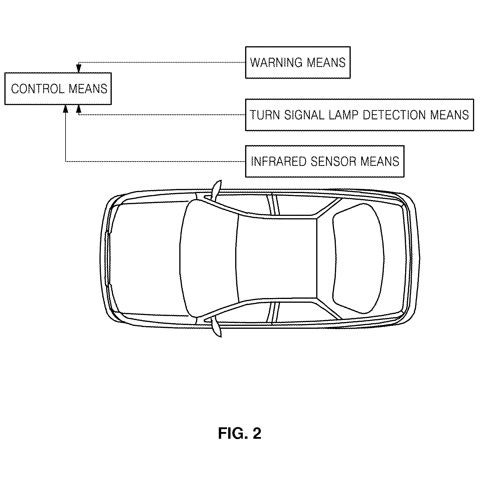
[0039]FIG. 4 is a diagram showing the construction of a collision avoidance system based on the detection of obstacles in the blind spots of a vehicle according to an embodiment of the present invention.

[0040]Referring to FIG. 4, the collision avoidance system based on the detection of obstacles in the blind spots of a vehicle according to an embodiment of the present invention includes a turn signal lamp detection means...


PUM


Abstract

The present invention relates to a collision avoidance system based on the detection of obstacles in the blind spots of a vehicle. The collision avoidance system includes turn signal lamp detection means for detecting whether a turn signal lamp of the vehicle is turned on. CCD camera means captures an image for a road environment, and outputs the captured image as road environment data, thus determining whether a current road environment indicates a winding road. Steering angle detection means detects a steering angle of the vehicle and outputs a resulting signal as a steering angle signal. Infrared sensor means transmits or receives infrared light to or from an obstacle present in the blind spot of the vehicle according to the steering angle signal, and outputs an obstacle detection signal. Warning means is configured to provide a warning of possibility of a collision between the obstacle and the vehicle to a driver. Control means automatically drives the warning means when the obstacle detection signal for the blind spot is received from the infrared sensor means in a case where a turn signal lamp is determined to be turned on by the turn signal lamp detection means, or where a lane change is determined to be performed by receiving the road environment data from the CCD camera means and the steering angle signal measured by the steering angle detection means.

Description

FIELD OF THE INVENTION[0001]The present invention relates, in general, to a collision avoidance system based on the detection of obstacles in the blind spots of a vehicle, and, more particularly, to a collision avoidance system based on the detection of obstacles in the blind spots of a vehicle, which detects an obstacle in a blind spot even when a vehicle changes lanes without turning on a turn signal lamp, and informs a driver of the detected obstacle in the blind spot, thus preventing collision accidents from occurring during traveling.BACKGROUND OF THE INVENTION[0002]The growth of the automobile industry is indicated by the development of an excellent engine, which can be called the heart of a vehicle, as the clearest evidence. Of course, various factors, such as an increase in fuel consumption ratio, and the prevention of environmental pollution, are taken into account, but the most important factor is a method of allowing a vehicle equipped with an excellent engine to travel a...

Claims


Application Information

Patent Timeline
Patent Type & Authority Applications(United States)
IPC IPC(8): B60Q1/00
CPCB60Q9/008G01S7/4813G01S17/026G01S17/936G01S2013/9332G08G1/16G08G1/167G01S2013/9315G01S17/04G01S17/931
Inventor KIM, HEUNG SEOPHUR, WON MOOKIM, HWA SIKPARK, JONG SUPKIM, YOUNG HOON
Owner CHE IL ELECTRIC WIREING DEVICES
Why Eureka
Try Eureka