Digital beam-forming apparatus and technique for a multi-beam global positioning system (GPS) receiver

Active Publication Date: 2008-11-27
SPATIAL DIGITAL SYST
View PDF9 Cites 53 Cited by
  • Summary
  • Abstract
  • Description
  • Claims
  • Application Information

AI Technical Summary

Benefits of technology

[0007]An advanced multiple-beam GPS receiving system is achieved that is capable of enhancing receiving sensitivity in the direction of GPS sources using multiple dynamic narrow beams with high gain, detecting multiple interference signals individually, and simultaneously suppressing gain in the antenna patterns of the multiple beams in the directions of interfering sources. The receiving antenna comprises an array of antenna elements that need not be co-planar. Key factors in the performance of the arr

Problems solved by technology

However, typical GPS receiving systems employ largely isotropic, low-gain antennas in order to simultaneously view large regions of the sky.
Besides wasting much of the antenna gain in directions with low payoff, such isotropic receivers also increase the system's susceptibility to interference signals, especially during aircraft final approach and landing.
The low broadcast power o

Method used


Image

  • Digital beam-forming apparatus and technique for a multi-beam global positioning system (GPS) receiver
  • Digital beam-forming apparatus and technique for a multi-beam global positioning system (GPS) receiver
  • Digital beam-forming apparatus and technique for a multi-beam global positioning system (GPS) receiver

Examples


Embodiment Construction

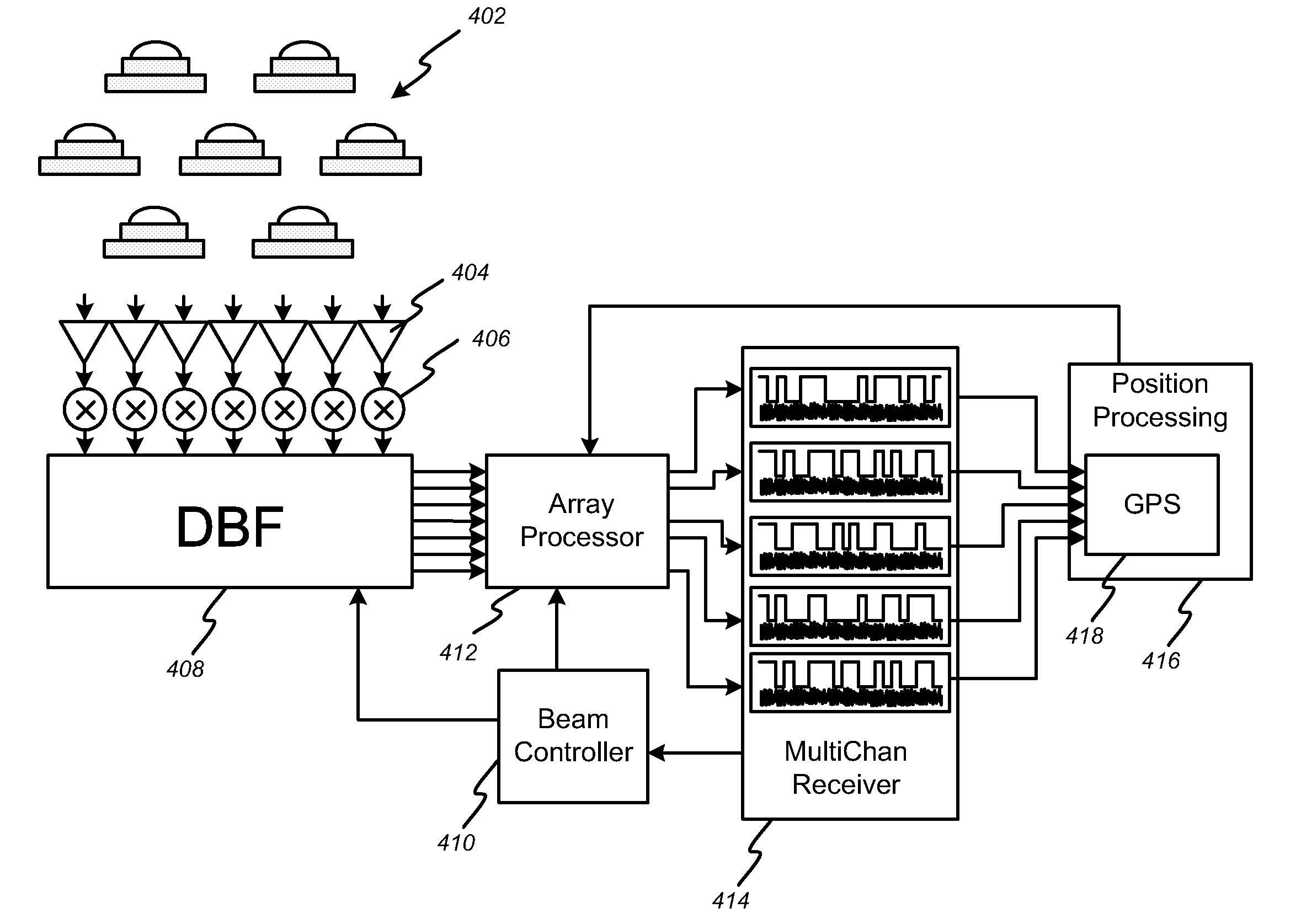
[0024]The invention provides an advanced multi-beam GPS receiving system that is capable of detecting multiple interference signals and suppressing gain in the antenna pattern in the interference directions. In the detailed description that follows, like element numerals are used to indicate like elements appearing in one or more of the figures.

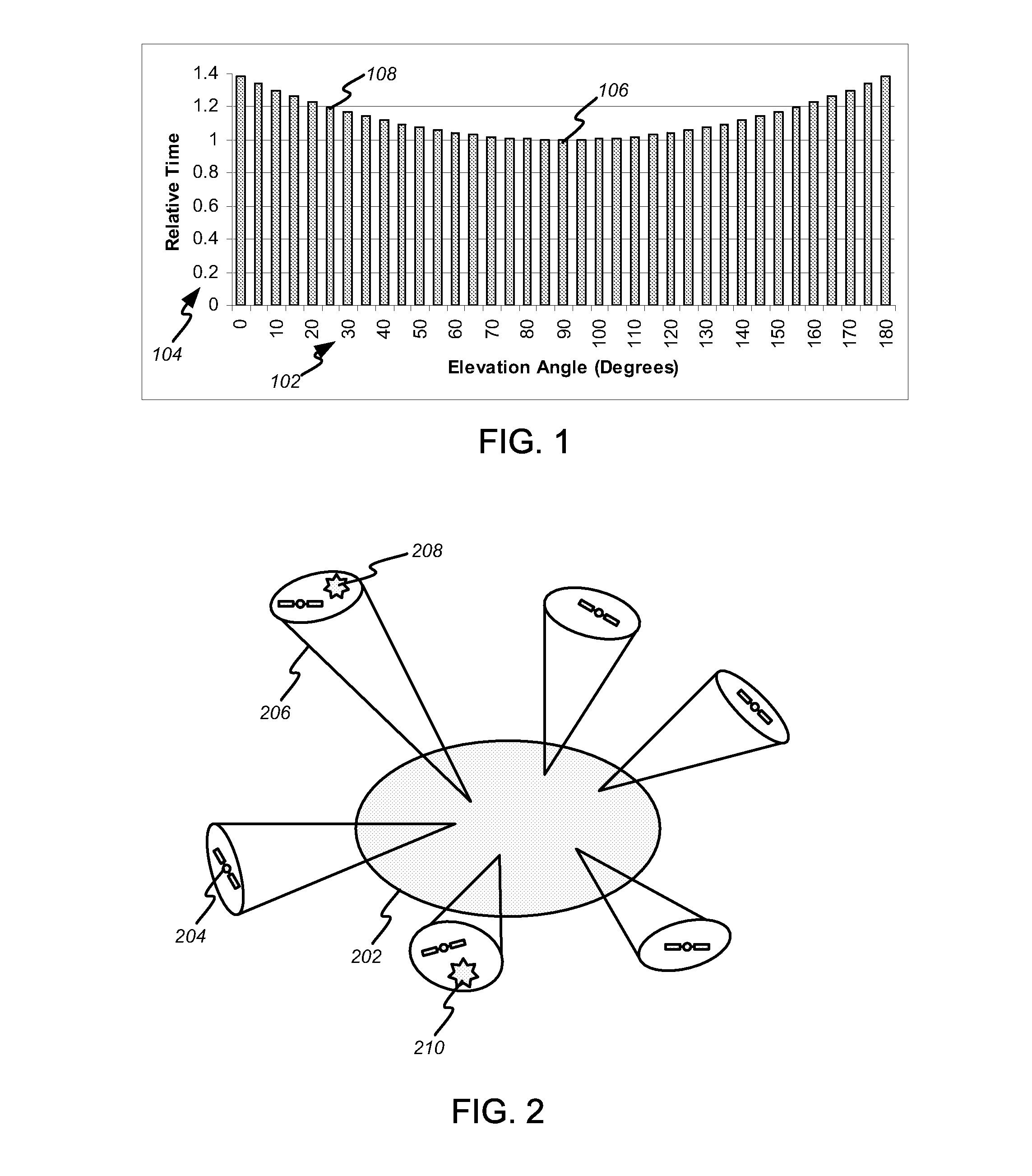
[0025]FIG. 1 illustrates that GPS constellation satellites tend to spend the majority of time relatively low on the horizon, from the point of view of an observer, either on the ground or on an airborne platform. In particular, the relative time spent 104 at a particular elevation angle 102 is plotted with respect to the time spent within five degrees of zenith 106, which is normalized to one. For example, bin 108 illustrates that the time a satellite is observed within five degrees of a twenty-five-degree elevation angle is approximately 20% greater than the time spent near zenith, for a satellite that passes through local zenith. For satell...


PUM


Abstract

An advanced multiple-beam GPS receiving system is achieved that is capable of simultaneously tracking multiple GPS satellites independently, detecting multiple interference signals individually, and suppressing directional gain in the antenna pattern of each beam in the interference directions. The GPS receiving system can be used for both planar and non-planar receiving arrays, including arrays that are conformally applied to the surface of a platform such as an aircraft. The GPS receiver combines spatial filtering and acquisition code correlation for enhanced rejection of interfering sources. Enhanced gain in the direction of GPS satellites and the ability to shape the beam patterns to suppress gain in the direction of interfering sources make the GPS receiving system largely insensitive to interfering and jamming signals that plague conventional GPS receivers.

Description

RELATED APPLICATION DATA[0001]This application claims the benefit, pursuant to 35 U.S.C. § 119(e), of U.S. provisional application Ser. No. 60 / 930,654, filed May 21, 2007.BACKGROUND OF THE INVENTION[0002]1. Field of the Invention[0003]The present invention relates to architectures and designs of Global Positioning System (GPS) receiving systems. In particular, the invention relates to the design of multiple-beam antennas using digital beam forming techniques to enable dynamic tracking of all GPS satellites within the field of view of the aperture.[0004]2. Description of Related Art[0005]It is well known in the art to use the NAVSTAR GPS satellite constellation to determine receiver location and obtain navigation information. The basic NAVSTAR constellation comprises twenty-four satellites orbiting in six orbital planes. Each orbital plane is inclined with respect to the equator by fifty-five degrees, and they are separated by sixty degrees right ascension. In each of the six orbital...

Claims


Application Information

Patent Timeline
IPC IPC(8): G01S5/14G01S7/40G01S19/05G01S19/11G01S19/21G01S19/28G01S19/29G01S19/35G01S19/36G01S19/46
CPCG01S19/21G01S19/28G01S19/35G01S19/36H01Q3/2605
Inventor CHANG, DONALD CHIN-DONG
Owner SPATIAL DIGITAL SYST
Why Eureka
Try Eureka