Liquid material arrangement method, color filter manufacturing method, and organic el display device manufacturing method
- Summary
- Abstract
- Description
- Claims
- Application Information
AI Technical Summary
Benefits of technology
Problems solved by technology
Method used
Image
Examples
first embodiment
Structure of Color Filter
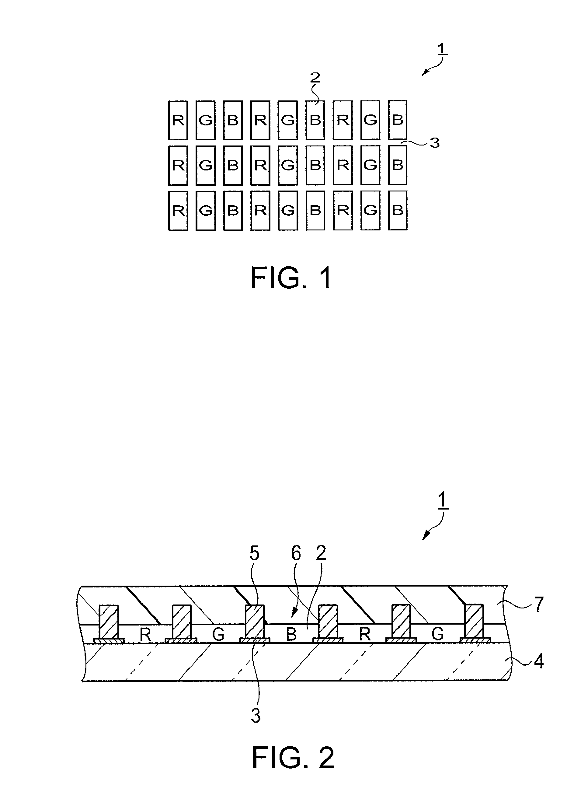
[0059]The structure of the color filter according to the present invention will first be described with reference to FIGS. 1 and 2. FIG. 1 is a plan view showing the configuration of the color filter. FIG. 2 is a sectional view showing the structure of the color filter.
[0060]The color filter 1 shown in FIGS. 1 and 2 is used in a color display panel, and has colored parts 2 that are formed so as to correspond to pixels of each color that include R (red), G (green), and B (blue) in the display panel; and light-blocking parts 3 that are formed in the regions between the colored parts 2. The colored parts 2 in the present embodiment have an arrangement and shape that correspond to a so-called striped pixel structure, but a different pixel structure may also be used. For example, a configuration may be adopted that is adapted to a structure that includes a color element other than R, G, and B, or to a delta structure.
[0061]The color filter 1 is provided with a gl...
modification example 1
[0112]Modification Example 1 will next be described with reference to FIGS. 10, 13A, 15, and 16, with emphasis on the differences between Modification Example 1 and the previously described embodiment.
[0113]FIG. 15 is a diagram showing the conditions for selecting deleted dots according to Modification Example 1. FIG. 16 is a diagram showing an example of the second dot pattern according to Modification Example 1.
[0114]In Modification Example 1, deleted dots are selected in step S15 based on the conditions shown in FIG. 15. Specifically, dots that correspond to nozzles other than the nozzle that corresponds to the dots already targeted for deletion in step S115 are selected by the first condition. By setting such a condition, since dots corresponding to each of the nozzles are deleted in substantially uniform ratios, the usage frequency of the nozzles with respect to a single partitioned region 6 is appropriately distributed. This configuration makes it possible to prevent fluctuati...
modification example 2
[0116]Modification Example 2 will next be described with reference to FIGS. 10, 13A, 17, and 18, with emphasis on the differences between Modification Example 2 and the previously described embodiment.
[0117]FIG. 17 is a diagram showing the conditions for selecting deleted dots according to Modification Example 2. FIG. 18 is a diagram showing an example of the second dot pattern according to Modification Example 2.
[0118]In Modification Example 2, deleted dots are selected in step S15 based on the conditions shown in FIG. 17. Specifically, dots that correspond to nozzles other than the nozzle that corresponds to the dots already targeted for deletion in step S15 are selected by the first condition, and dots of the third scan are selected by the second condition. By setting such conditions, dots corresponding to each of the nozzles are deleted in substantially uniform ratios, the usage frequency of the nozzles is appropriately distributed, the amount of the liquid material arranged in ...
PUM
 Abstract
Description
Claims
Application Information
 - R&D
- Intellectual Property
- Life Sciences
- Materials
- Tech Scout
- Unparalleled Data Quality
- Higher Quality Content
- 60% Fewer Hallucinations
Browse by: Latest US Patents, China's latest patents, Technical Efficacy Thesaurus, Application Domain, Technology Topic, Popular Technical Reports.
© 2025 PatSnap. All rights reserved.Legal|Privacy policy|Modern Slavery Act Transparency Statement|Sitemap|About US| Contact US: help@patsnap.com


