Electrical connector with clip mechanism

a technology of electric connectors and clips, applied in the field of clips, can solve the problems of still being vulnerable to deformation or warpage, and achieve the effect of preventing the cpu chip from warpag

Inactive Publication Date: 2008-11-27
HON HAI PRECISION IND CO LTD
View PDF11 Cites 20 Cited by
  • Summary
  • Abstract
  • Description
  • Claims
  • Application Information

AI Technical Summary

Benefits of technology

[0010]It is therefore there is a need to provide clip mechanism in which downward force are evenly distribute to both the die and the substrate thereby efficiently prevent the CPU chip from warpage.

Problems solved by technology

Even it is rigid, but is still vulnerable to deform or warp if downward force applied thereon is not evenly distributed.

Method used


Image

  • Electrical connector with clip mechanism
  • Electrical connector with clip mechanism
  • Electrical connector with clip mechanism

Examples


first embodiment

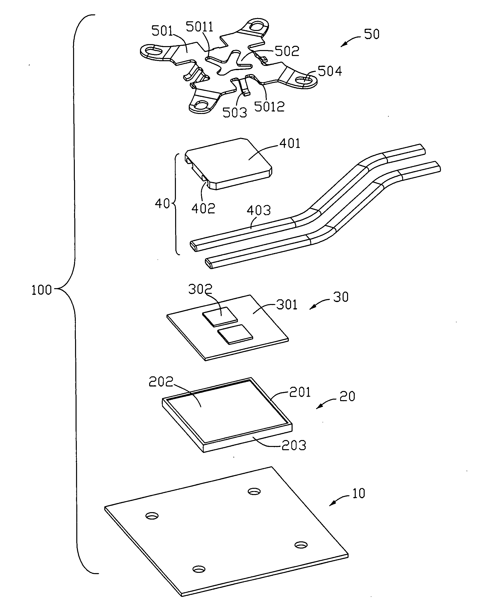
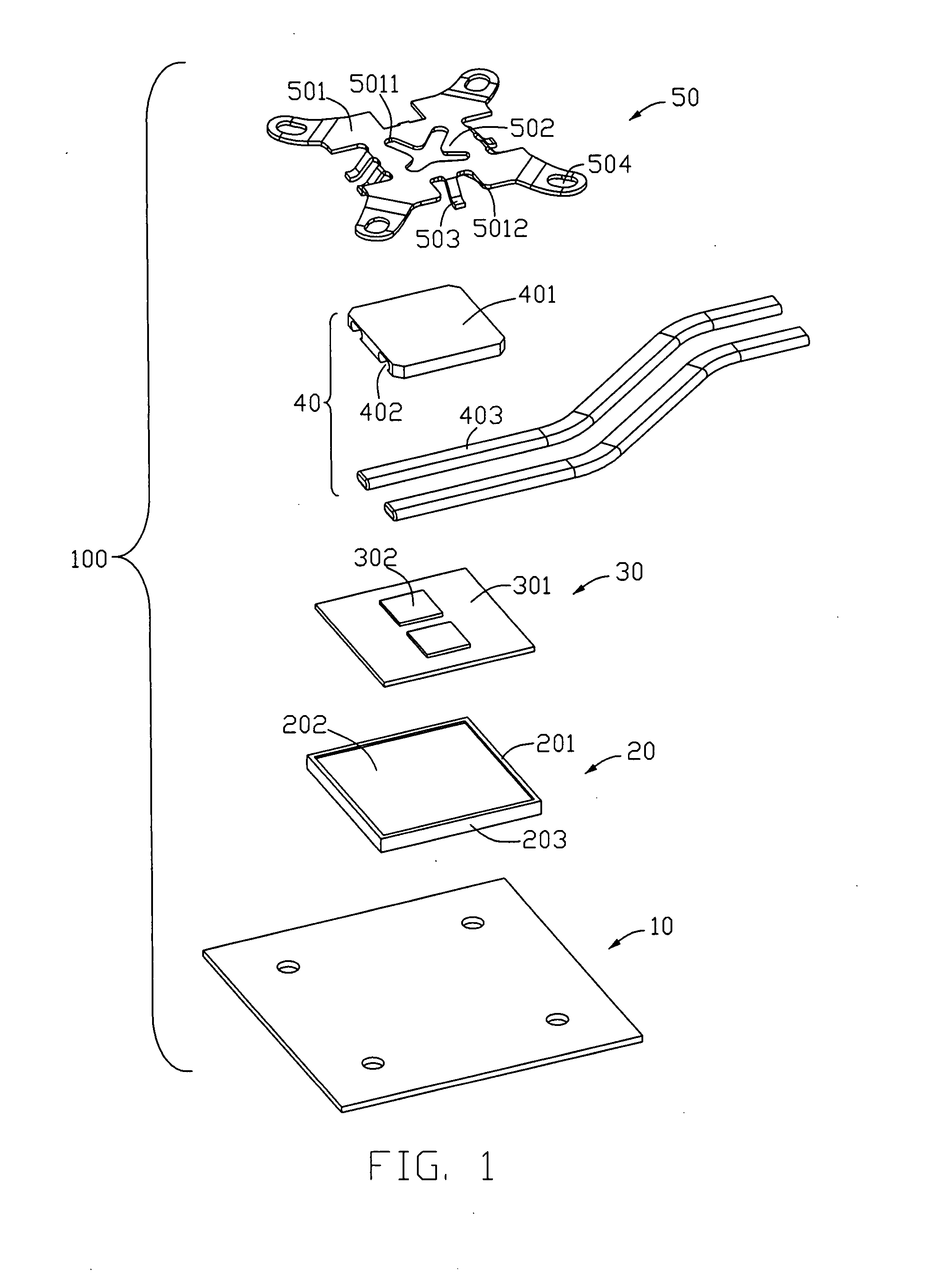
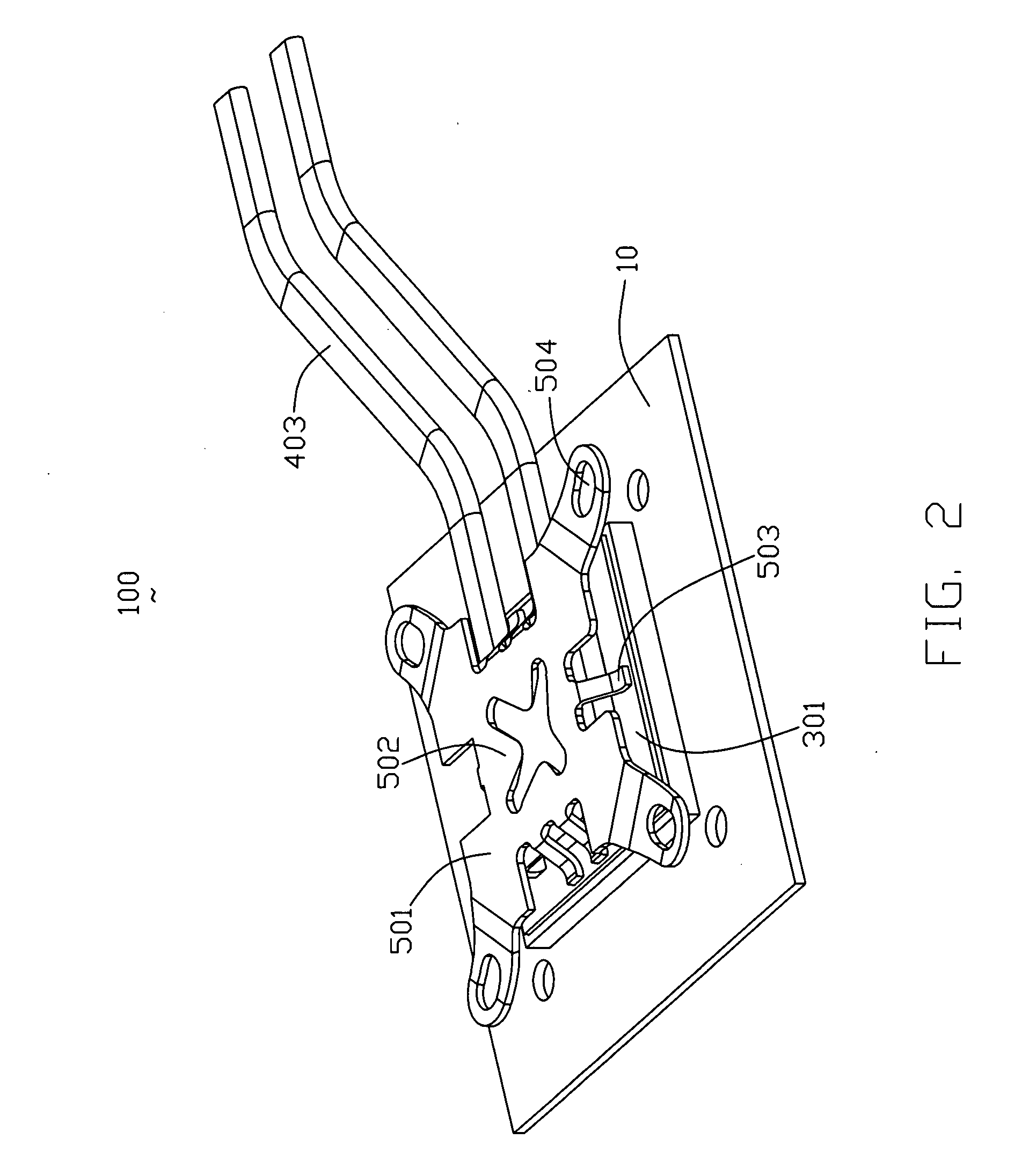
[0022]Referring to FIG. 1 to FIG. 2, an electrical connector assembly 100 in accordance with the present invention includes a printed circuit board 10, an electrical socket 20 having a contact engaging portion 202 extending beyond a top surface thereof, an IC module 30, electrically disposed on the socket and electrically contacted with the contact engaging portions 202, and a heatsink assembly 40, including a clip set 50 securely attached to the printed circuit board 10 pressing the IC module 30 toward the socket to ensure reliable electrical connection between the IC module 30 and the contact engaging portion 202.

[0023]Individual elements of the electrical connector assembly 100 will now be described in greater detail. The electrical socket 20 includes a substantially rectangular insulating housing 201, the housing 201 includes a supporting surface to accept an electronic component, for example an IC module 30, thereon and opposite facing mounting surface to a print circuit board ...

second embodiment

[0027]Referring to FIG. 3 and FIG. 4, an electrical connector assembly 800 in accordance with the present invention includes an electrical socket 80 having a contact engaging portion 801 extending beyond a top surface thereof, an IC module 802, electrically disposed on the socket and electrically contacted with the contact engaging portions 801, and a heatsink assembly, including a clip set 804 securely attached to the printed circuit board pressing the IC module 802 toward the socket to ensure reliable electrical connection between the IC module 802 and the contact engaging portion 801.

[0028]As shown in FIG. 3, the heatsink assembly also comprises a heat spreader 8031 and a heat pipe 8032, and the heat pipe 8032 attached to the heat spreader 8031 directly. The electrical connector assembly 800 also comprises a clip mechanism 804, the clip set 804 has a set of first pressing finger 8041 and a set of second pressing finger 8042, but the set of first and second pressing fingers (8041,...


PUM


Abstract

Provided a clip set (50) for pressing a CPU toward LGA contacts of a CPU socket comprises, a rigid body having an elongate base (501) with upper and lower edges. A set of first pressing finger (502) extends from the upper edge traversally and away from the base. Each of the first pressing fingers includes a first pressing pad located at a first plane. A set of second pressing finger (503) extends from and away from the base, and includes a second pressing pad located at a second plane differential to the first plane. The set of first and second pressing fingers are dimensioned to be located in two different levels so as to assert downward pressure to a die (302) of the CPU and a substrate (301) of the CPU, respectively.

Description

BACKGROUND OF THE INVENTION[0001]1. Field of the Invention[0002]The present invention relates to a clip, and more particularly to a clip including at least two pair of pressing fingers asserting downward force evenly to a die and a substrate of a CPU chip therefore preventing potential warpage of the CPU.[0003]2. Background of the Invention[0004]U.S. Pat. No. 5,722,848 issued to Lai on Mar. 3, 1998 discloses a typical connector socket, and which is generally referred to as ZIF (Zero Insertion Force) socket. In generally, the socket includes a base with a plurality of contacts assembled therein, and a cover moveably attached to the base. A lever along with a cam mechanism is arranged between the base and cover at a head portion so as to drive the cover from a first position to a second position. When the lever is located in a vertical position, the cover is located at the first position, in which a hole in the cover is completely in align with a corresponding passageway in the base. ...

Claims


Application Information

Patent Timeline
Patent Type & Authority Applications(United States)
IPC IPC(8): H05K7/20H01R4/50
CPCH01R4/48H01R4/50
Inventor MA, HAO-YUNSZU, MING LUNWERTZ, DERRELL
Owner HON HAI PRECISION IND CO LTD
Why Eureka
Try Eureka