Light emitting diode lamp

a technology of light-emitting diodes and lamps, which is applied in the direction of point-like light sources, semiconductor devices of light sources, and lighting and heating apparatus, etc., can solve the problems of reduced heat dissipation efficiency and ineffective reduction of led temperature, so as to improve heat dissipation efficiency and reduce the thermal resistance of the interface caused by the package interface on the heat dissipation path. , the effect of dissipating hea

Inactive Publication Date: 2008-11-27
ADVANCED CONNECTEK INC +1
View PDF6 Cites 82 Cited by
  • Summary
  • Abstract
  • Description
  • Claims
  • Application Information

AI Technical Summary

Benefits of technology

[0018]In the LED lamp of the present invention, the LED chips are directly packaged on the substrate with the heat dissipation function, so as to dissipate heat generated during the operation of the LED chips by the substrate made of metal material, thereby improving the heat dissipation effi

Problems solved by technology

Currently, the package design of the LED lamp is still based upon multilayer package, such that a interface thermal resistance is generated due to a plurality of package interfaces existed on the heat dissipation path, and as a result,

Method used


Image

  • Light emitting diode lamp
  • Light emitting diode lamp
  • Light emitting diode lamp

Examples


Embodiment Construction

[0025]Reference will now be made in detail to the present embodiments of the invention, examples of which are illustrated in the accompanying drawings. Wherever possible, the same reference numbers are used in the drawings and the description to refer to the same or like parts.

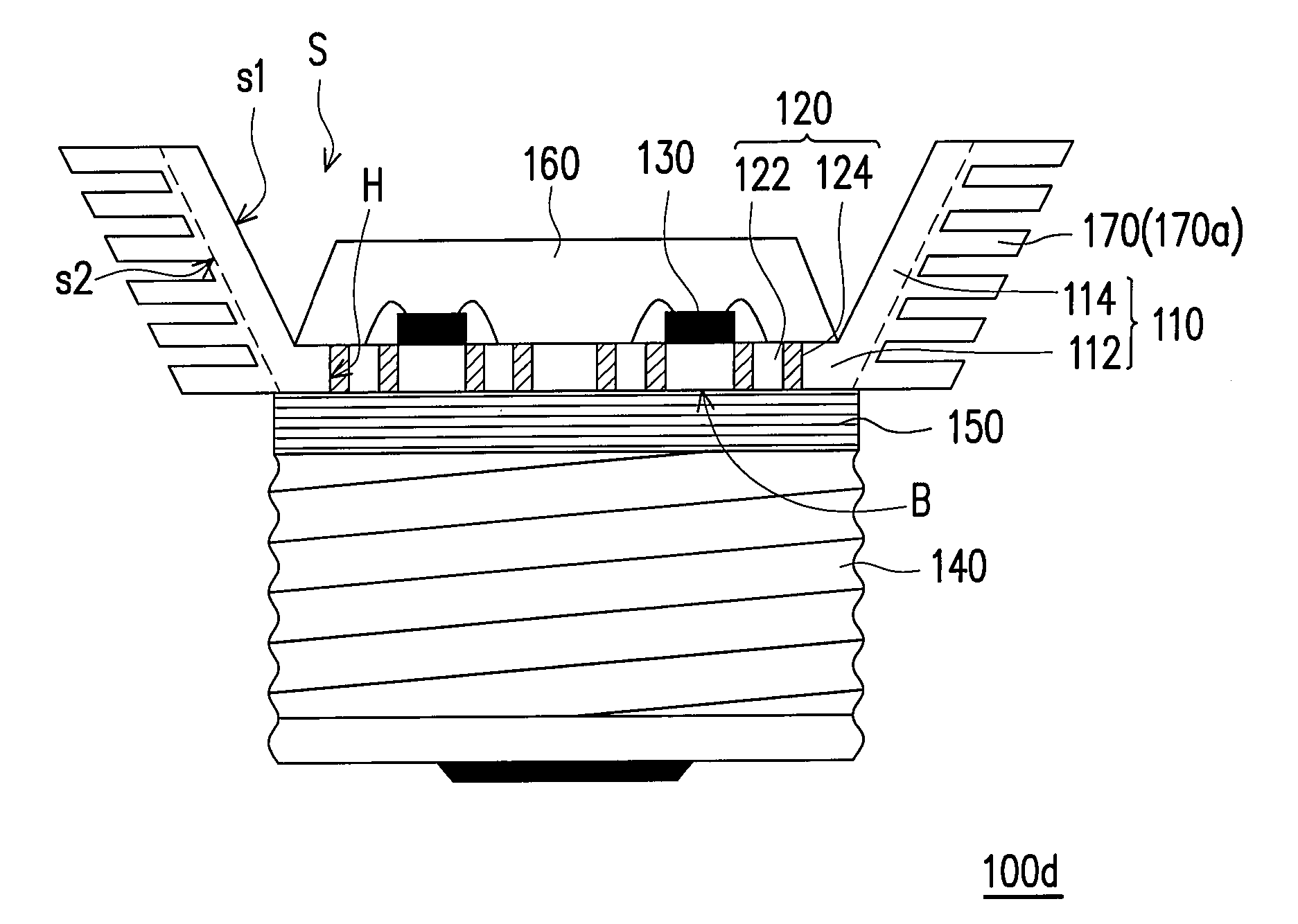
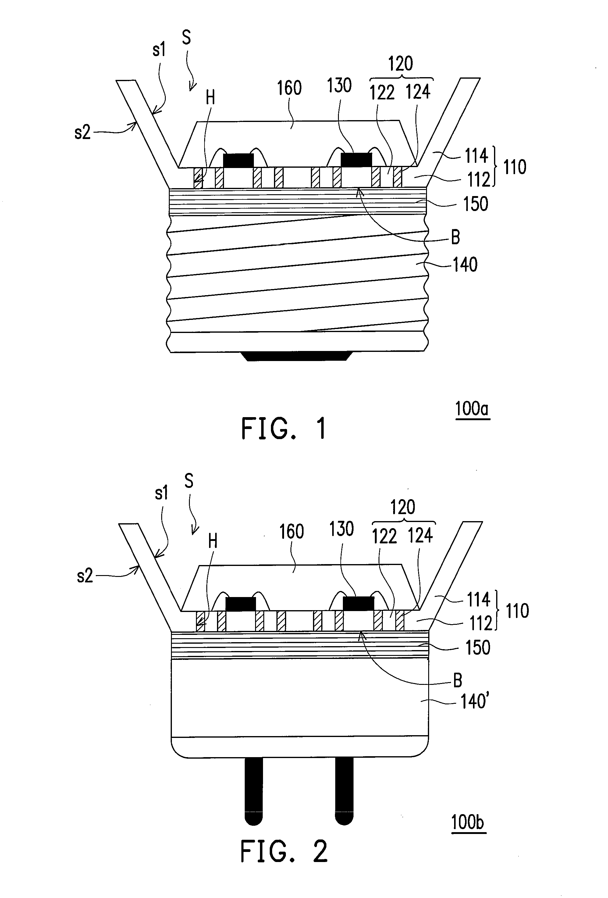
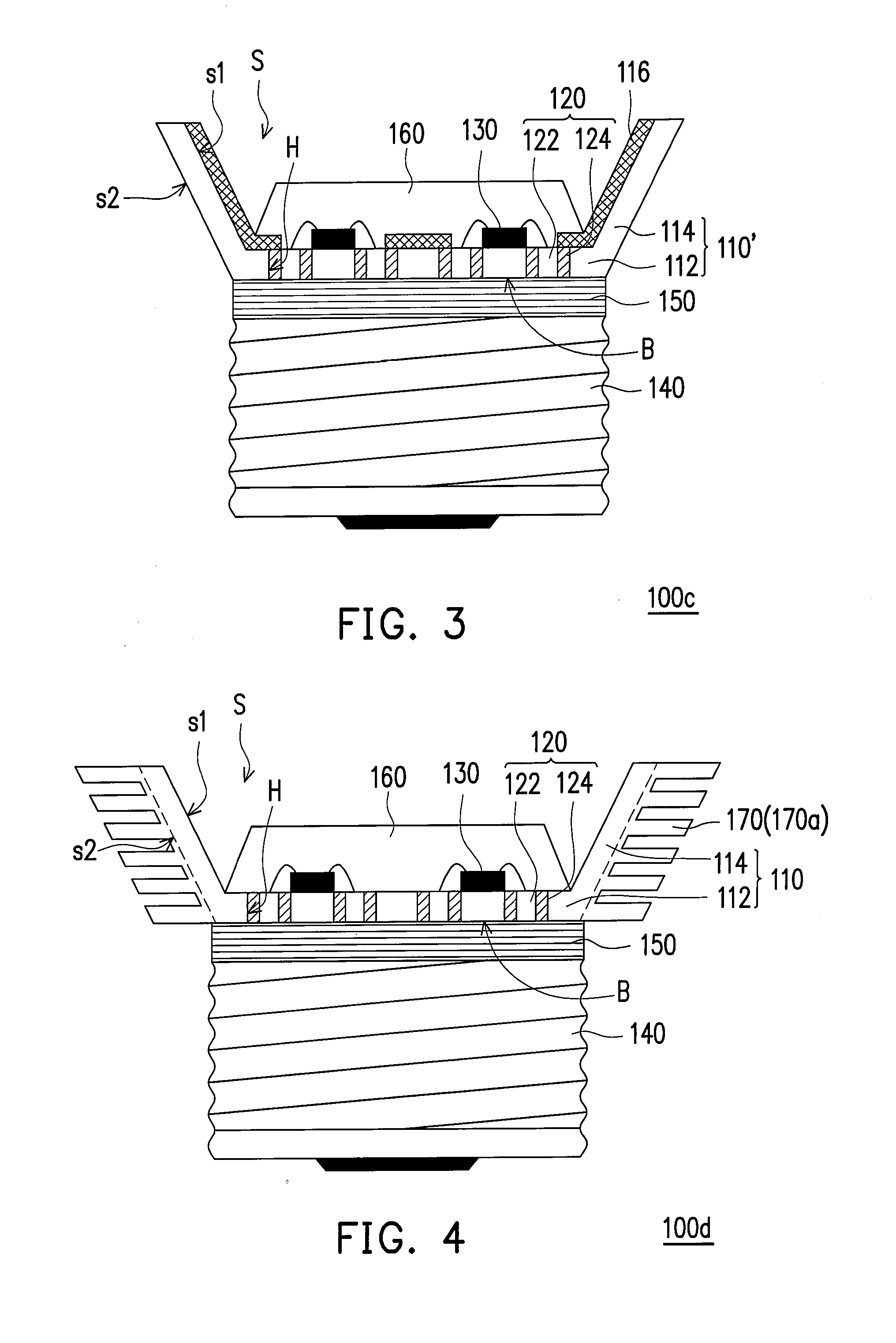
[0026]FIG. 1 is a schematic cross-sectional view of an LED lamp according to an embodiment of the present invention. Referring to FIG. 1, an LED lamp 100a mainly includes a substrate 110, a plurality of wire units 120, a plurality of LED chips 130, a lamp cap 140, and a control circuit module 150. Each element of the LED lamp 100a and the connection relation between the elements are described below with reference to the accompanying drawings.

[0027]The substrate 110 has an inner surface s1, an outer surface s2, and a bottom part B. The substrate 110 has a carrying portion 112 and a ring frame 114 connected to a periphery of the carrying portion 112, and the carrying portion 112 and the ring frame 114 are formed...


PUM


Abstract

A light emitting diode (LED) lamp including a substrate, a plurality of wire units, a plurality of LED chips, a lamp cap, and a control circuit module is provided. The substrate has a carrying portion and a ring frame connected to the periphery thereof. The carrying portion has a plurality of openings. The wire units are respectively disposed inside the openings. Each wire unit has a wire and an insulating material covering the periphery of the wire, such that the wire is electrically isolated from the substrate. The LED chips are disposed on the carrying portion, and each LED chip is electrically connected to the corresponding wires. The lamp, cap is disposed on the bottom of the substrate and has two power contacts. The control circuit module is disposed between the substrate and the lamp cap and electrically connected to wires and power contacts, to control operations of LED chips.

Description

CROSS-REFERENCE TO RELATED APPLICATION[0001]This application claims the priority benefit of Taiwan application serial no. 96118290, filed on May 23, 2007. The entirety the above-mentioned patent application is hereby incorporated by reference herein and made a part of specification.BACKGROUND OF THE INVENTION[0002]1. Field of the Invention[0003]The present invention generally relates to a light emitting diode (LED) lamp, in particular, to an LED lamp directly packaging LED chips on a substrate.[0004]2. Description of Related Art[0005]LED is a semiconductor device, and the light emitting chip is mainly made of Group III-V chemical elements, for example, GaP, GaAs, and other compound semiconductors. The light emitting principle is to convert the electric energy into lights, that is, a current is applied to the compound semiconductor, and then, through combining electrons with holes, the excess energy is released in the form of lights, so as to achieve the light emitting effect. The li...

Claims


Application Information

Patent Timeline
IPC IPC(8): F21V7/00F21V29/00F21Y103/37H01L33/62H01L33/64
CPCF21Y2101/02F21V29/006H01L2224/48091F21V29/767F21K9/137F21V29/505F21V29/745H01L2924/00014F21K9/233F21Y2115/10F21K9/68
Inventor LIN, SHUN-TIANHUANG, JYUN-WEI
Owner ADVANCED CONNECTEK INC
Why Eureka
Try Eureka