Acoustic Wave Sensor

a technology of acoustic waves and sensors, applied in the field of acoustic wave sensors, can solve the problems of inability to detect the distance to an object relative to the wave receiving device, the inability to distinguish between the reflected waves from these two objects on the basis, and the inability to detect the distance to the object with respect to the object positioned within a predetermined distance from the wave receiving device. , to achieve the effect of increasing the angular resolution

Inactive Publication Date: 2008-11-27
PANASONIC CORP
View PDF6 Cites 20 Cited by
  • Summary
  • Abstract
  • Description
  • Claims
  • Application Information

AI Technical Summary

Benefits of technology

[0019]In this way, when the electric capacitance microphones are used as the wave receiving devices, a Q factor of resonance characteristic of each wave receiving device is smaller than a Q factor of resonance characteristic of the piezoelectric device. In comparison with the conventional acoustic wave sensor using the piezoelectric devices as the wave transmitting device and the wave receiving devices, the dead zone caused by reverberation component included in the wave receiving signal outputted from each wave receiving device can be shortened, and the angular resolution can be increased.
[0020]Furthermore, when the acoustic wave generator which generates the acoustic wave by applying the thermal impacts to the air is used as the wave generating d

Problems solved by technology

Therefore, for example, in the acoustic wave sensor for detecting a distance to an object, it is impossible to detect the distance to the object with respect to the object positioned within a predetermined distance from the wave receiving devices.
As just described, in the acoustic wave sensor using the piezoelectric device as the wave transmitting device, since a dead zone caused by the reverberation component included in the acoustic wave transmitted from the wave transmitting device is longer, a distance to an object relatively near to the wave receiving devices cannot be detected.
In such a case, it is difficult to distingu

Method used


Image

  • Acoustic Wave Sensor
  • Acoustic Wave Sensor
  • Acoustic Wave Sensor

Examples


first embodiment

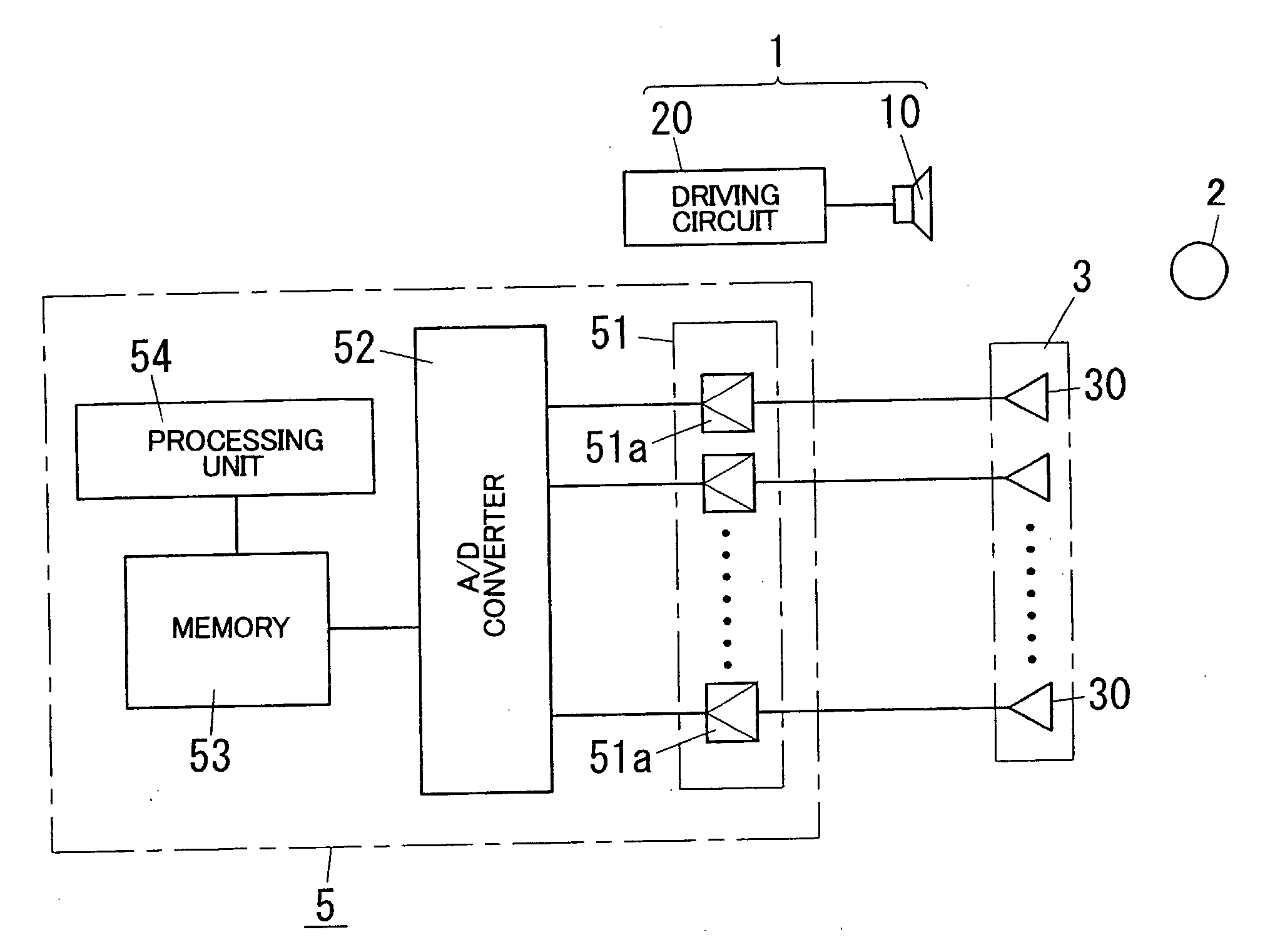
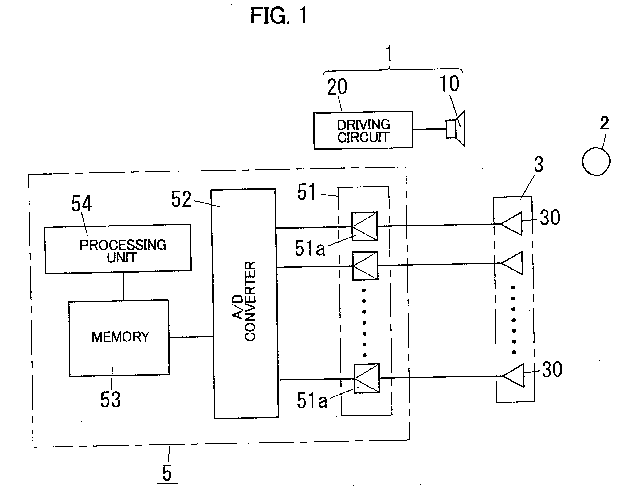
[0050]An acoustic wave sensor in accordance with a first embodiment of the present invention is described with reference to figures. The first embodiment relates to the acoustic wave sensor detecting both of a distance to an object and an orientation where the object is located in order to recognize three dimension locus of the object.

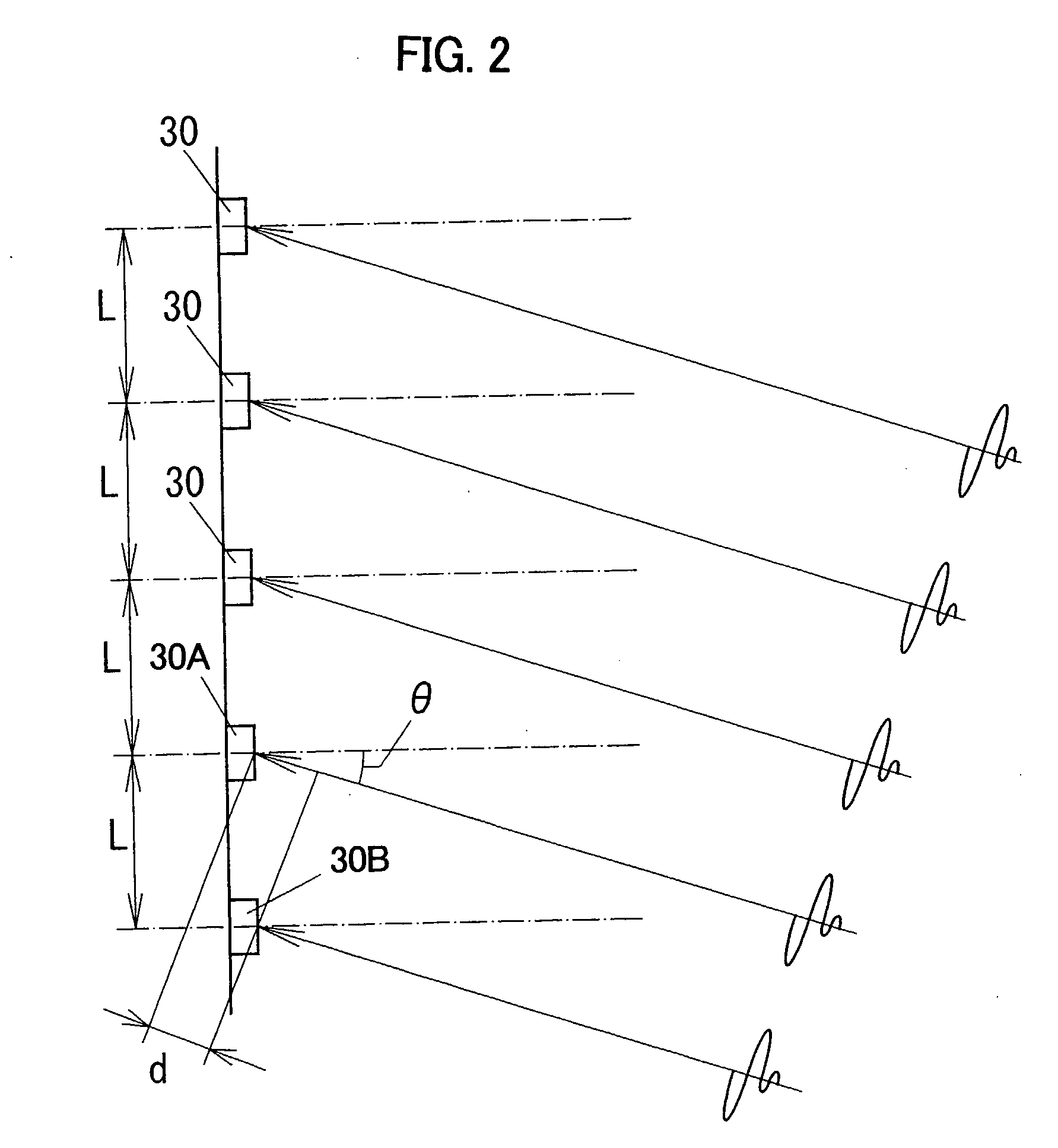
[0051]As shown in FIG. 1, the acoustic wave sensor of the first embodiment comprises a wave transmitter 1 for transmitting an acoustic wave (a compressional wave) intermittently in the air, a wave receiver 3 for receiving reflected waves reflected by an object 2, and a signal processing circuit 5 for processing output of the wave receiver 3. The acoustic wave sensor is configured to detect the distance to the object 2 and the orientation where the object 2 is located on the basis of terms from a time when an acoustic wave is transmitted from the wave transmitter 1 to times when the acoustic waves reflected by the object 2 are received by the wave recei...

second embodiment

[0090]Subsequently, an acoustic wave sensor in accordance with a second embodiment of the present invention is described with reference to the figures. The second embodiment relates to the acoustic wave sensor for detecting both of a distance to an object and an orientation where the object is located in order to recognize three dimension locus of the object. Basic configuration of the acoustic wave sensor of the second embodiment is substantially the same as that of the acoustic wave sensor of the first embodiment, but configurations of a wave transmitting device 10 and a driving circuit 20 constituting the wave transmitter 1 are different, as shown in FIG. 9. Therefore, only the difference is explained, and illustration and description of the other configurations are omitted.

[0091]The wave transmitting device 10 in the second embodiment is a thermally induced acoustic wave generator generating an acoustic wave by thermal impact, and has a pair of electrodes 19 opposing with each o...

third embodiment

[0095]Subsequently, an acoustic wave sensor in accordance with a third embodiment of the present invention is described. The third embodiment relates to the acoustic wave sensor for detecting both of a distance to an object and an orientation where the object is located in order to recognize three dimension locus of the object. Basic configuration of the acoustic wave sensor of the third embodiment is substantially the same as that of the acoustic wave sensor of the first embodiment, but configurations of a wave transmitting device 10 and a driving circuit 20 constituting the wave transmitter 1 are different. Therefore, only the difference is explained.

[0096]In a wave transmitter 1 of the third embodiment, a thermally induced acoustic wave generator used as the wave transmitting device 10 comprises a member to be heated having a low heat capacity and a low heat conductance, and a laser device such as a semiconductor laser for heating the member to be heated by irradiation of a laser...


PUM


Abstract

In an acoustic wave sensor for detecting a distance to an object and an orientation where the object is located with using acoustic waves, an acoustic wave generating device generating an acoustic wave by applying thermal impact to the air with no mechanical vibration is used as a wave transmitting device, and an electric capacitance microphone converting variation of pressure due to acoustic wave to variation of an electric signal is used as each wave receiving device. Therefore, dead zone caused by reverberation component included in the acoustic wave transmitted from the wave transmitting device and dead zone caused by reverberation component included in wave receiving signals outputted from the wave receiving devices can be shortened and angular sensitivity of the acoustic wave sensor can be increased, in comparison with a conventional acoustic wave sensor using piezoelectric devices as the wave transmitting device and the wave receiving devices.

Description

TECHNICAL FIELD[0001]The present invention relates to an acoustic wave sensor utilizing acoustic wave for detecting a distance to an object and / or an orientation where the object is located.BACKGROUND ART[0002]As for such a kind of acoustic wave sensor, for example, Japanese Laid-Open Patent Publication No. 2002-156451 discloses an acoustic wave sensor of reflected wave formula. In the acoustic wave sensor of reflected wave formula, compressional wave such as ultrasonic wave is intermittently transmitted from a wave transmitter having a wave transmitting device to a medium, and reflected wave reflected by an object is received by a wave receiver having a wave receiving device. A distance to the object and an orientation where the object is located is detected on the basis of a time difference from the transmission of the compressional wave to the receiving of the reflected wave.[0003]On the other hand, for example, Japanese Laid-Open Patent Publication No. 2003-279640 discloses an a...

Claims


Application Information

Patent Timeline
IPC IPC(8): G01S15/06
CPCB06B1/02G01H11/06G01L9/0025G01S3/808G01S7/524G01S7/526G01S3/80
Inventor YAMANAKA, HIROSHIWATABE, YOSHIFUMIHONDA, YOSHIAKIKITADA, KOUSAKUKAWADA, HIROSHIOHTSUKA, TOMOOSAWADA, KAZUOGOTO, HIROMICHI
Owner PANASONIC CORP
Why Eureka
Try Eureka