
Centrifugal air blower

a centrifugal blower and centrifugal technology, which is applied in the direction of machines/engines, stators, liquid fuel engines, etc., can solve the problems of reducing the efficiency of the blower and unsatisfactory noise levels, and achieve the effect of reducing the noise level and reducing the recirculation of air

Inactive Publication Date: 2008-11-27
HUSQVARNA CONSUMER OUTDOOR PROD N A
View PDF12 Cites 18 Cited by
  • Summary
  • Abstract
  • Description
  • Claims
  • Application Information

AI Technical Summary

Benefits of technology

[0006]According to one aspect, the present invention concerns a centrifugal air blower that incorporates certain features that reduce the noise levels generated by the circulation of air within the centrifugal blower and reduce the recirculation of air within the centrifugal blower compared to the case where these features are not present.

Problems solved by technology

A centrifugal blower, however it may be powered, whether by electricity or the burning of fuel for example, can generate undesirable levels of noise as a result of the high-velocity circulation of the air within the blower.
In addition, it can be the case that the internal structure of the centrifugal blower causes a portion of the circulating air within the blower to be recirculated past the blower discharge opening rather than be discharged from the blower through the blower discharge opening, thereby reducing the efficiency of the blower.

Method used


Image

  • Centrifugal air blower
  • Centrifugal air blower
  • Centrifugal air blower

Examples


Embodiment Construction

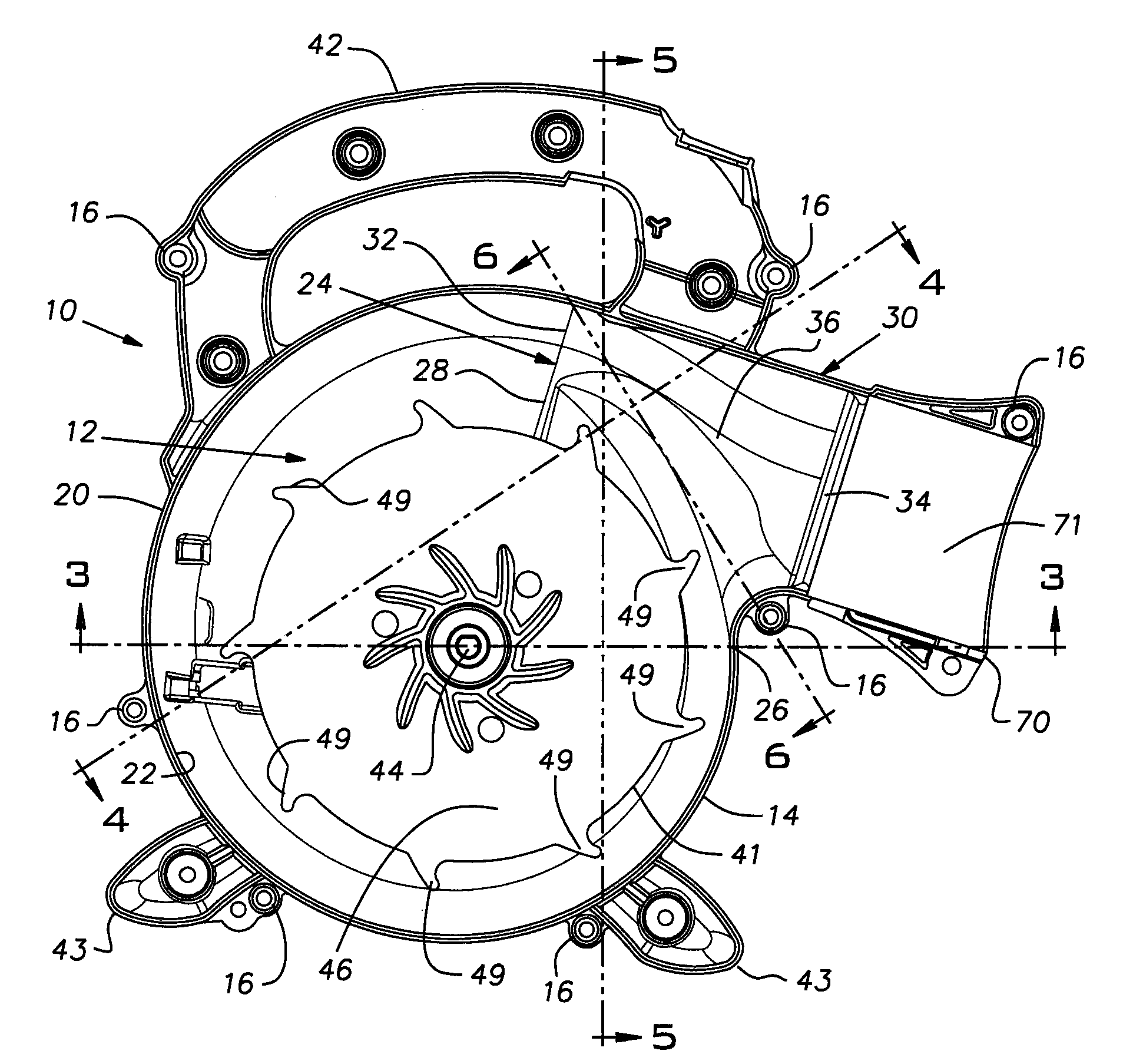
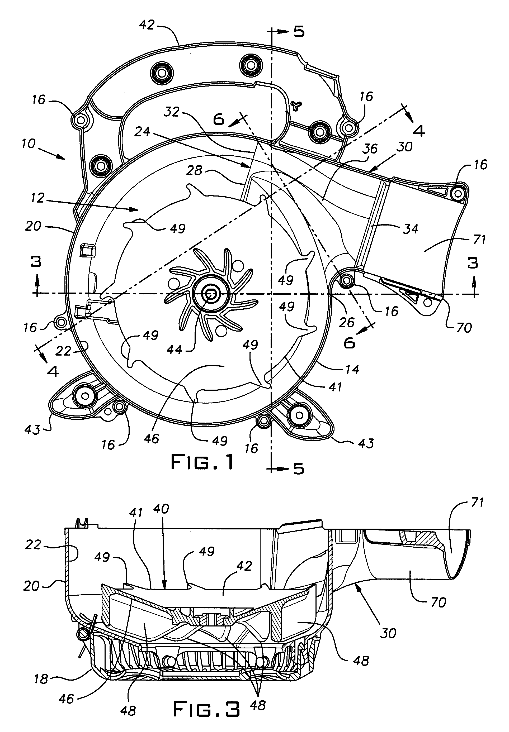
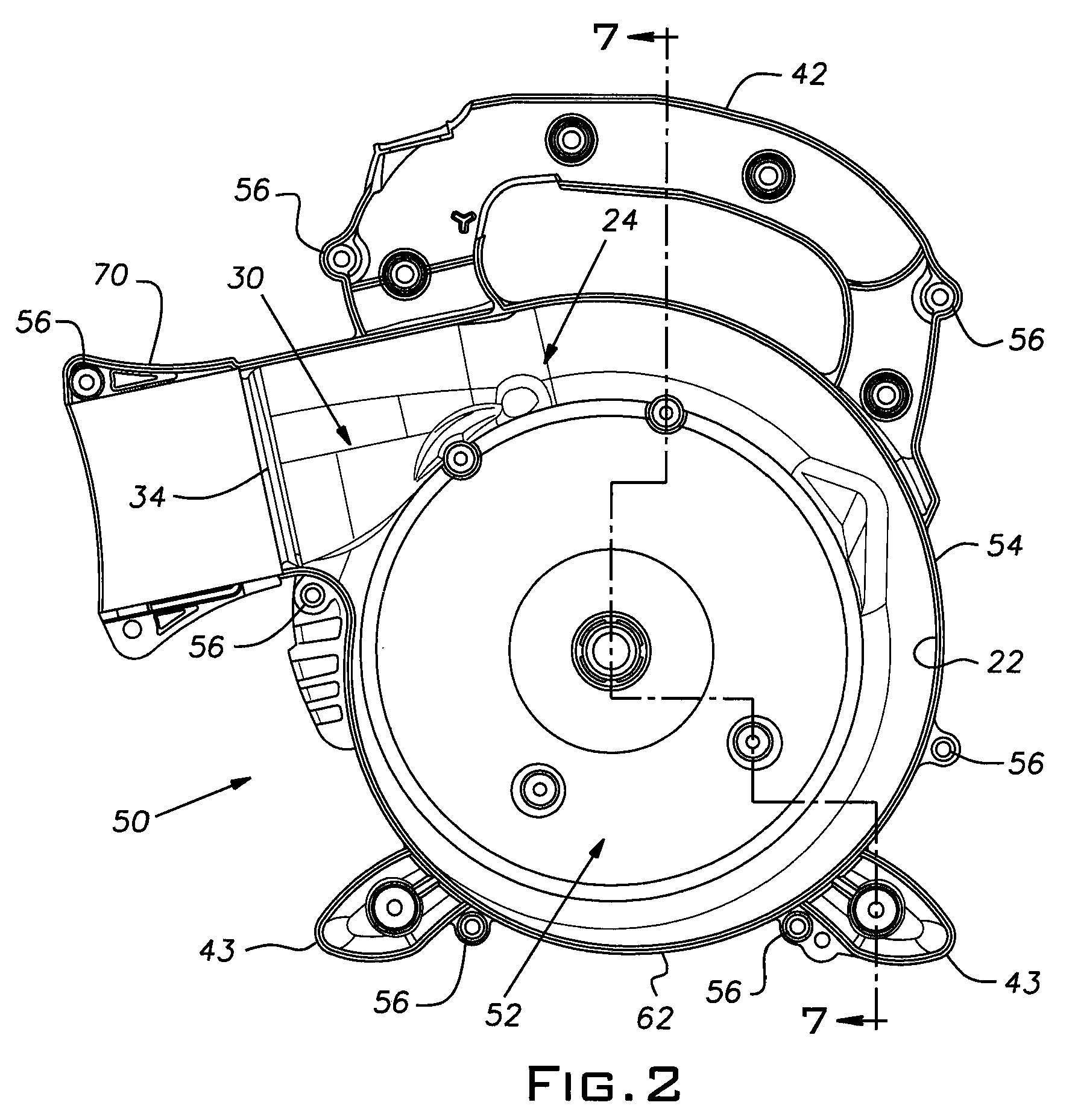
[0019]Referring first to FIGS. 1 and 2 of the drawings, there are shown in FIG. 1 a first sub-assembly of an embodiment of a centrifugal air blower, indicated generally at 10, and in FIG. 2 a second sub-assembly of the same embodiment of the centrifugal air blower, indicated generally at 50. In FIGS. 1 and 2, internal faces or sides 12 and 52 of the first and second sub-assemblies, respectively, face the viewer so as to reveal certain parts of the first and second subassemblies that are located within the interior of the centrifugal air blower when the blower is assembled. In assembling the centrifugal air blower, the internal side 12 of the first sub-assembly 10 and the internal side 52 of the second sub-assembly 50 are brought together in a face-to-face attitude and the matching perimeters 14 and 54 of the first sub-assembly and the second sub-assembly, respectively, aligned with one another and brought into engagement so that the first sub-assembly and second sub-assembly can be ...


PUM


Abstract

A centrifugal blower includes a main scroll portion and a scroll opening through which air is discharged. A transitional portion conducts air discharged through the scroll opening away from the blower. The transitional portion includes an internal passageway that provides for the smooth passage of air essentially without causing any abrupt changes in the direction of the flow of the air through the passageway. An impeller assembly can be mounted within the main scroll portion for rotation so as to circulate the air in a spiral path within the main scroll portion and force the air through the scroll opening and the passageway in the transitional portion. The impeller assembly can have a platen that has a perimeter and a plurality of impeller blades mounted at the platen for rotation with the platen. Each impeller blade can have a distal end that extends beyond the perimeter of the platen.

Description

CROSS-REFERENCE TO RELATED APPLICATION[0001]The benefit of U.S. Provisional Application No. 60 / 940,224 filed on May 25, 2007 is claimed for this application.BACKGROUND OF THE INVENTION[0002]The present invention relates generally to centrifugal blowers. In particular, the invention relates to centrifugal blowers having a scroll-type casing or housing within which is disposed an impeller assembly that, upon rotation, draws air to the blower interior from the exterior of the blower, circulates the air in a spiral path within the scroll-type housing and then discharges the air back to the exterior of the blower through an opening in the scroll-type housing.[0003]The need to move air exists in a variety of circumstances such as, for example, in connection with the operation of heating, air-conditioning and ventilating equipment as well as the operation of lawn-care and landscaping equipment. Centrifugal blowers are often used for that purpose. Typically, the centrifugal blowers include ...

Claims


Application Information

Patent Timeline
Patent Type & Authority Applications(United States)
IPC IPC(8): F01D1/02
CPCF04D25/084F04D29/422F04D29/4226
Inventor GLORE, THOMAS G.SOLINSKI, ANDREW L.MURNAN, JUSTINBILIMEK, ROBERT L.
Owner HUSQVARNA CONSUMER OUTDOOR PROD N A
Learn More