Oil pump driving mechanism

a technology of oil pump and driving mechanism, which is applied in the direction of fluid gearing, gearing, hoisting equipment, etc., can solve the problems of inability to easily mount the torque converter itself on the input shaft, and the inability to easily insert the engaging pawl into the insertion hole, so as to reduce the friction resistance between the engaging pawl and the side face of the first sprock

Active Publication Date: 2008-11-27
JATCO LTD +1
View PDF25 Cites 13 Cited by
  • Summary
  • Abstract
  • Description
  • Claims
  • Application Information

AI Technical Summary

Benefits of technology

[0010]According to this invention, by providing the friction reducing mechanism on at least one of the side face of the first sprocket and the engaging pawl of the torque converter, frictional resistance between the engaging pawl and the side face of the first sprocket can be reduced if the engaging pawl comes into contact with the side face of the first sprocket when the engaging pawl is inserted into the recessed portion of the first sprocket while rotating the engaging pawl, for example. As a result, positioning between the engaging pawl and the recessed portion of the first sprocket can be performed easily, and the engaging pawl can be inserted into the recessed portion of the first sprocket easily.

Problems solved by technology

Hence, when the drive resistance of the oil pump is small, for example, frictional resistance between the engaging pawl and the side face of the drive sprocket causes the drive sprocket and the engaging pawl to co-rotate, making it impossible to insert the engaging pawl into the insertion hole easily, and as a result, the torque converter itself cannot easily be mounted on the input shaft.

Method used


Image

  • Oil pump driving mechanism
  • Oil pump driving mechanism
  • Oil pump driving mechanism

Examples


first embodiment

[0019]this invention will now be described.

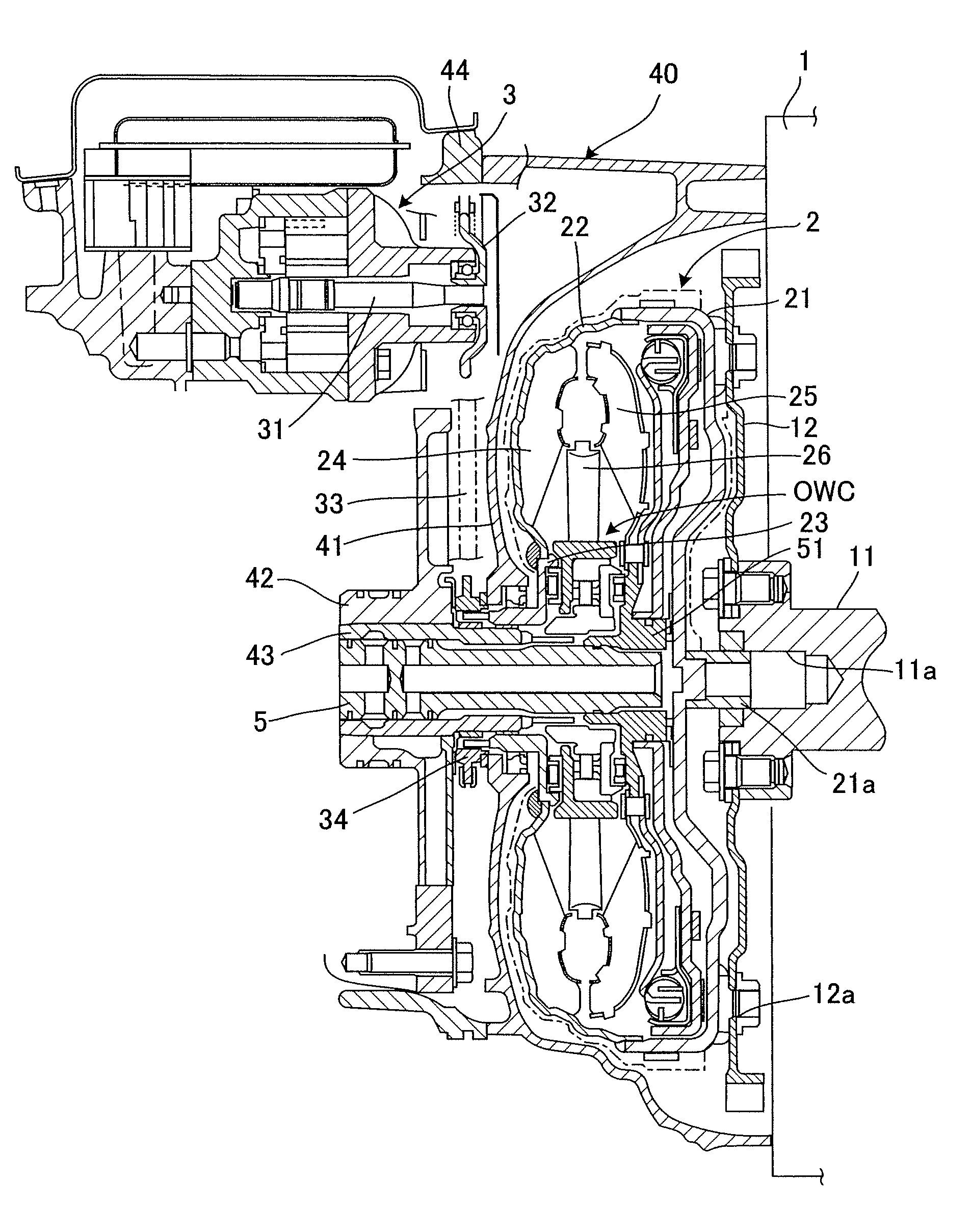
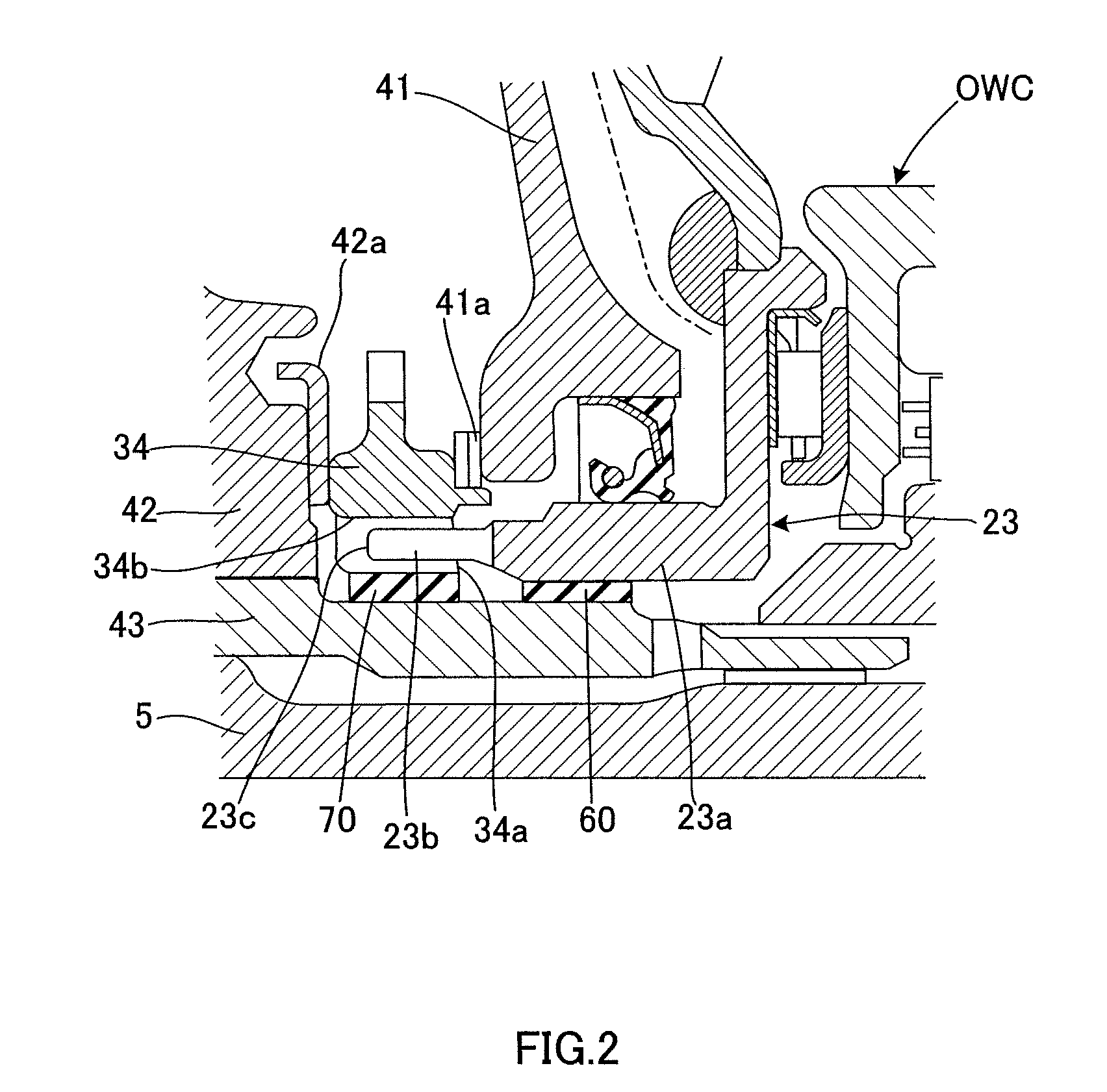
[0020]FIG. 1 is a partial cross-sectional view showing the vicinity of a torque converter in an automatic transmission comprising an oil pump driving mechanism. A transmission unit housing 40 attached to an engine 1 is provided with a torque converter housing 41 that houses a torque converter 2, a cover 42 and a stator shaft 43 that rotatably support an input shaft 5, the torque converter 2, and so on, and an oil pump housing 44 that houses an oil pump 3. The cover 42 according to this embodiment is formed from a material such as aluminum to achieve weight reduction, while the stator shaft 43 is formed from an iron-based material to secure enough strength to function as a support. The oil pump 3 according to this embodiment is disposed in a radially detached position from the input shaft 5.

[0021]An engine drive plate 12 is connected to a crankshaft 11 that outputs a driving force of the engine 1 by a bolt. A linking portion 12a is provided ...

second embodiment

[0047]It should be noted that the projecting portion 81 may be provided on the end portion of the engaging pawl 23b. Further, frictional resistance may be reduced in the second embodiment by implementing any surface treatment that achieves a reduction in frictional resistance between the side face 80a and the projecting portion 81 and end face 23c.

[0048]The effects of the second embodiment of this invention will now be described.

[0049]In this embodiment, the annular projecting portion 81 is provided on the side face 80a of the first sprocket 80 such that when the end face 23c of the engaging pawl 23b comes into contact with the first sprocket 80 during assembly of the torque converter 2, the projecting portion 81 projecting from the first sprocket 80 comes into contact with the end face 23c. Thus, frictional resistance between the projecting portion 81 and the end face 23c can be reduced, thereby suppressing co-rotation with the first sprocket 80 and facilitating insertion and fitt...


PUM


Abstract

When an engaging pawl 23b is fitted into a recessed portion 34b of a first sprocket 34, which is linked by a chain 33 to a second sprocket 32 that drives an oil pump 3 disposed at a radial detached from a torque converter 2, frictional resistance between a side face 34a of the first sprocket 34 and an end face 23c of the engaging pawl 23b is reduced by tapering the side face 34a of the first sprocket 34.

Description

FIELD OF THE INVENTION[0001]This invention relates to an oil pump driving mechanism.BACKGROUND OF THE INVENTION[0002]The techniques described in JP2003-156130A and JP2005-325979A are well-known as conventional techniques for driving an oil pump. Specifically, a torque converter sleeve is provided so as to extend axially to an inner diameter side of an impeller shell that is coupled to a converter cover of a torque converter by welding or the like, and an engaging pawl is provided on an end portion of the torque converter sleeve.[0003]The engaging pawl is inserted into an insertion hole provided in a side face of a drive sprocket supported on a transmission main body side, and transmits the driving force of an engine by contacting an inner side wall of the insertion hole.[0004]A chain is looped around the drive sprocket (first sprocket) and a driven sprocket (second sprocket) supported on the oil pump side, and the chain transmits the rotation of the drive sprocket to the driven spro...

Claims


Application Information

Patent Timeline
Patent Type & Authority Applications(United States)
IPC IPC(8): F16H55/30F16H41/30F16H57/023F16H57/04
CPCF16H41/24F16H57/0434F16H55/30
Inventor MAKITA, KENICHI
Owner JATCO LTD
Why Eureka
Try Eureka