Apparatus and method for direct vertebral rotation

a technology of direct vertebral rotation and apparatus, which is applied in the field of aligned linkage, can solve the problems of difficult to see and correct, rotational misalignment of vertebrae, and surgeon's assistants facing the difficult task, and achieve the effect of facilitating gripping and facilitating the gripping of lever arms

Active Publication Date: 2008-11-27
STRYKER EURO OPERATIONS HLDG LLC
View PDF11 Cites 41 Cited by
  • Summary
  • Abstract
  • Description
  • Claims
  • Application Information

AI Technical Summary

Benefits of technology

[0022]In another aspect of the present invention, the interior faces of the jaws have a surface to facilitate gripping the extension tubes or lever arms. In a preferred embodiment, this may be a compliant material such as rubber. The coefficient of friction of such a material should facilitate the gripping of the lever arms, and the material may also include compliancy such that the lever arms are, upon undergoing a clamping force, forced into the material for gripping purposes. The compliance also allows the lever arms to be gripped at various angles and positions along the length of the jaws.
[0023]In another aspect of the present invention, a method includes the use of the above broadly-described instrument by surrounding a plurality of lever arms with a normally open instrument, positioning the instrument about the lever arms, closing the instrument such that the jaws clamp the lever arms, and manually applying a torque and otherwise manipulating the instrument in order to manipulate the lever arms and thus the vertebra to which the lever arms are connected, directly or indirectly. The clamping of the jaws may achieve an initial desired alignment of the lever arms and vertebrae and then the entire assembly of the lever arms and vertebrae may be further rotated to the final position. The method may also include the steps of fixing spinal rods or other fixation devices arranged with respect to the vertebra to maintain the vertebra in the aligned position, and subsequently releasing the clamping instrument and removing the same from the lever arms.

Problems solved by technology

More difficult to see and correct is rotational misalignment of the vertebrae about the axis in the defined along the length of the spine.
The surgeon and the surgeon's assistants face the difficult task of manually rotating and aligning the various lever arms to eventually fasten the pedicle screw assemblies to rods and form a construct holding the vertebrae in the desired alignment.
A polyaxial screw also has a limited extent of free travel and can create torque on the vertebra once the range of movement of the head is exceeded.

Method used


Image

  • Apparatus and method for direct vertebral rotation
  • Apparatus and method for direct vertebral rotation
  • Apparatus and method for direct vertebral rotation

Examples


Embodiment Construction

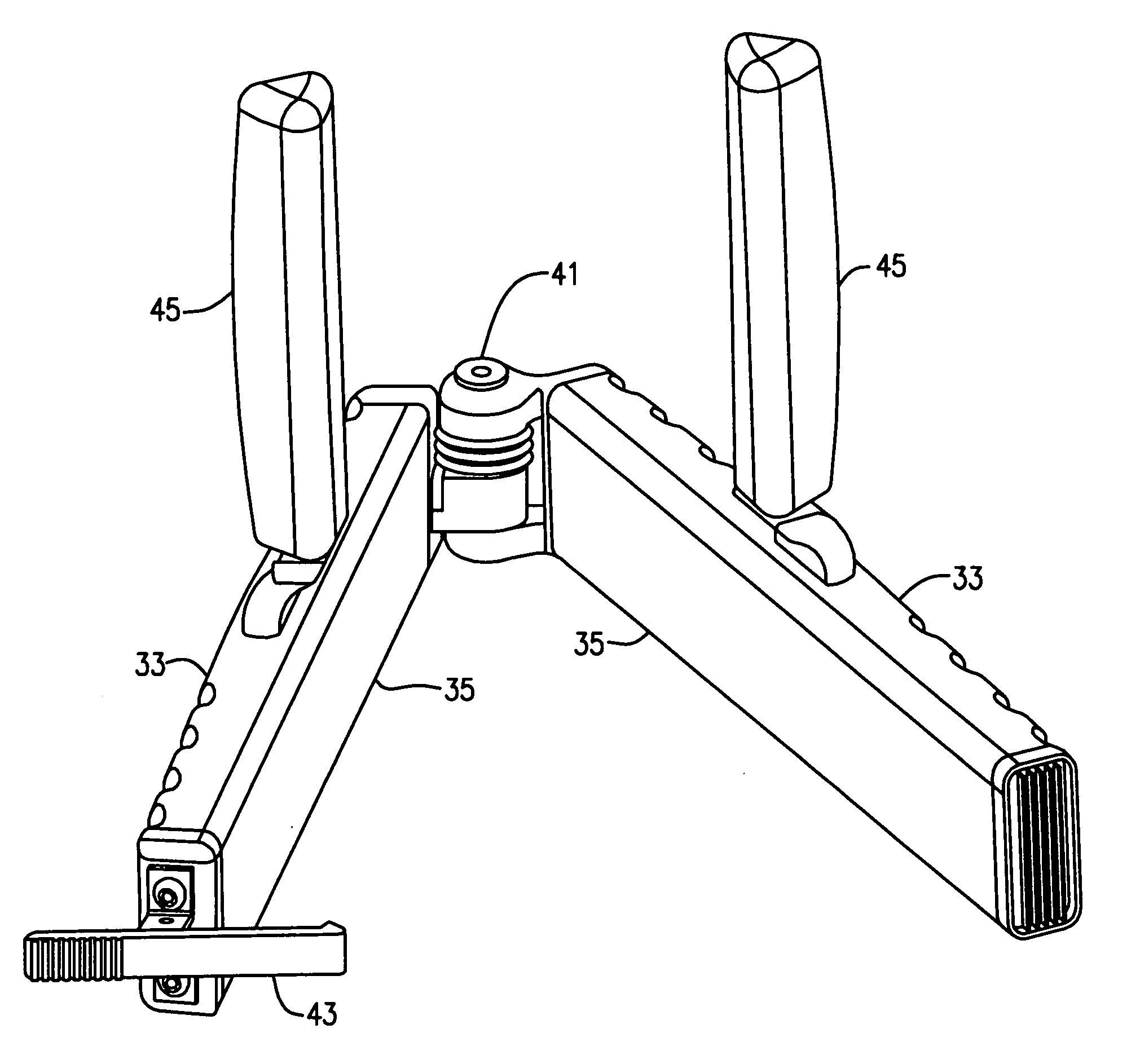
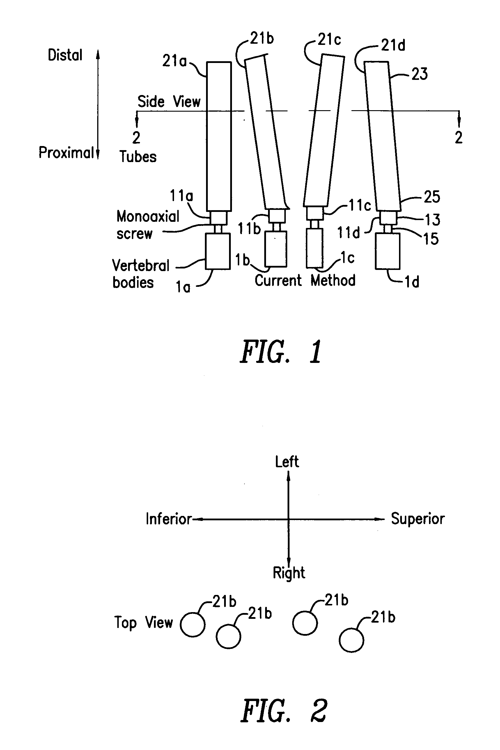
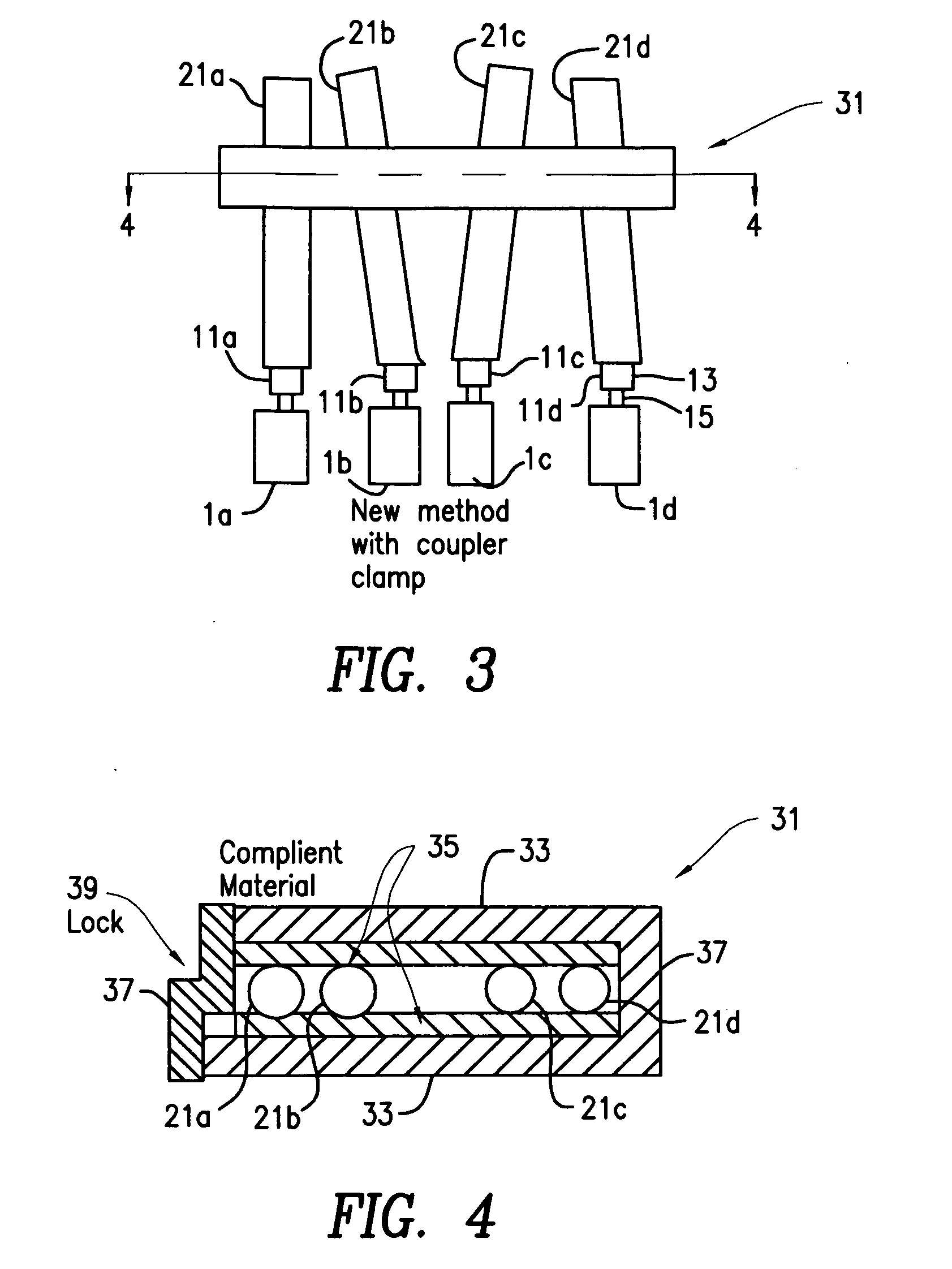
[0031]Referring to FIG. 1, the portion of the spine illustrated includes a first vertebra 1a, which may be the T10 (Tenth Thoracic) vertebra of a patient, a second vertebra 1b, which may be the T9 (Ninth Thoracic) vertebra of a patient, a third vertebra 1c, which may be the T8 (Eighth Thoracic) vertebra of a patient, and a fourth vertebra 1d, which may be the T7 (Seventh Thoracic) vertebra of a patient. The systems and methods described hereafter may be applicable to any vertebra or vertebrae of the spine and / or the sacrum (not shown). In this application, the term “vertebra” may be broadly interpreted to include the sacrum although rotation is only attempted relative to the sacrum and the sacrum itself is not rotated.

[0032]Pedicle screw assemblies 11a-11d 9 collectively screws 11) are implanted in the associated pedicles of the vertebrae 1a-1d. In one of many pedicle screw arrangements, pedicle screw assemblies 11a-11d each have a cage 13 shaped to receive a rod and a set screw tha...


PUM


Abstract

An instrument for spinal rotation that aligns and holds direct vertebral rotation (DVR) lever arms relative to each other to achieve an initial axial alignment of a segment of vertebrae and allows the final DVR rotation by rotating the instrument and lever arms together. A method of direct vertebral rotation that allows rotating the vertebrae to be aligned relative to each other, and collectively rotating the vertebrae to be aligned relative to adjacent spinal segments by rotating the direct vertebral rotation instrument. A system for direct vertebral rotation having at least two pedicle screws. The system also includes at least two levers attachable to the pedicle screws and a clamping instrument configured to clamp the levers.

Description

CROSS-REFERENCE TO RELATED APPLICATIONS[0001]This application claims the benefit of the filing date of U.S. Provisional Patent Application No. 60 / 930,770 filed May 18, 2007, the disclosure of which is hereby incorporated herein by reference.FIELD OF THE INVENTION[0002]The present invention relates generally to an alignment linkage such as a direct vertebral rotation instrument for creating, restraining and / or maintaining horizontal rotation of the vertebrae during posterior spinal fusion operations. The present invention also relates to a method for creating, restraining and / or maintaining horizontal rotation of the vertebrae during posterior spinal fusion operations.BRIEF DESCRIPTION OF THE PRIOR ART[0003]During spine surgery for conditions such as scoliosis, the surgeon seeks to achieve a three-dimensional correction of the spinal column shape by realigning and instrumenting the vertebrae in order to achieve an eventual fusion of the vertebral bodies in the desired alignment. Typi...

Claims


Application Information

Patent Timeline
Patent Type & Authority Applications(United States)
IPC IPC(8): A61F5/00A61B17/04A61B17/00A61B19/00
CPCA61B17/7074A61B17/708A61B17/7077A61B17/7047A61B17/7079A61B17/7091A61B17/86
Inventor CHOI, ANDY WONYONGSCHMITZ, MICHAEL L.SUK, SE-IL
Owner STRYKER EURO OPERATIONS HLDG LLC
Why Eureka
Try Eureka