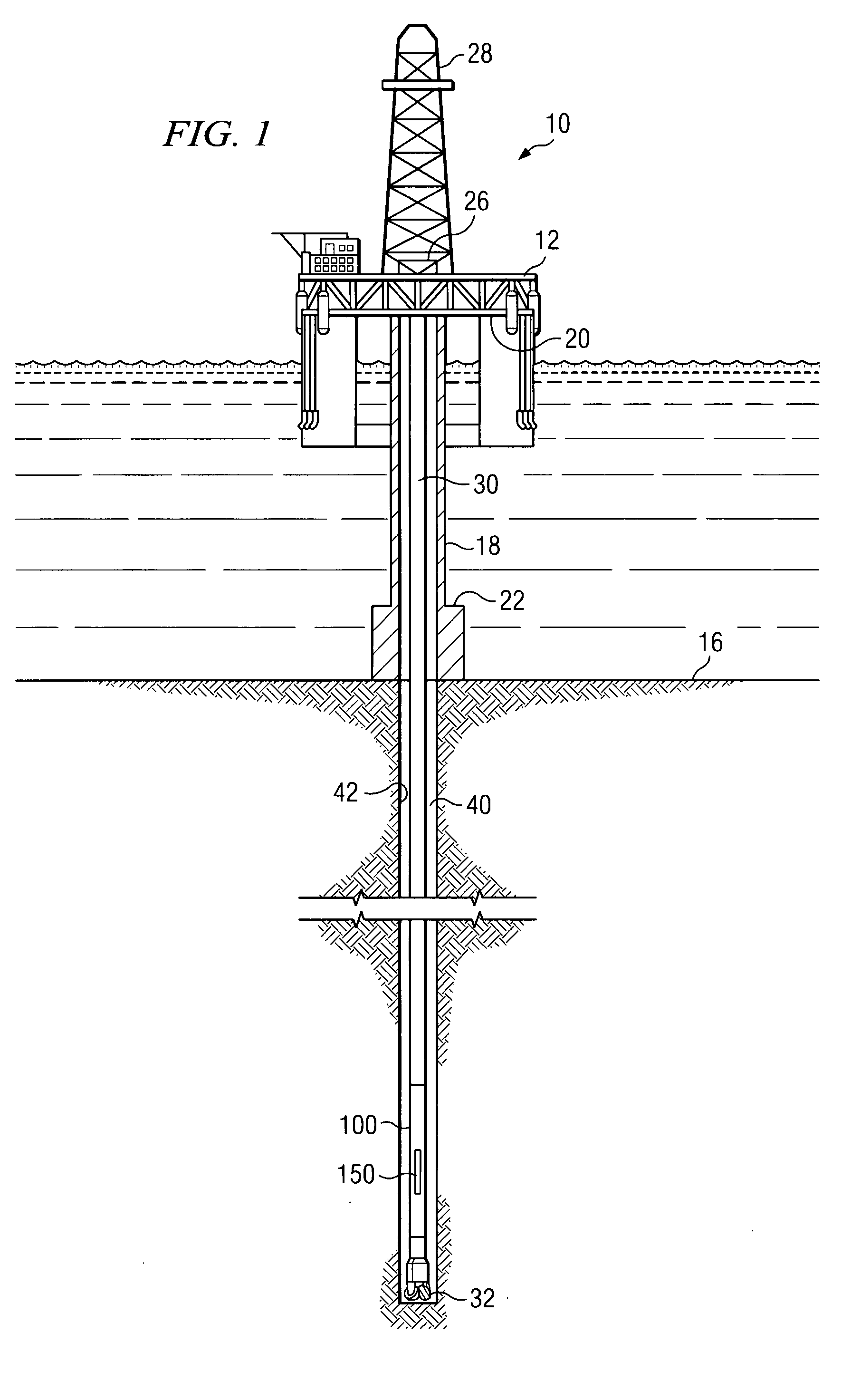
Angular position sensor for a downhole tool

a technology of angular position sensor and tool, which is applied in the field of downhole tools, can solve the problems of conventional magnetometers that are not ideally suited to imaging applications, electrical power is scarce, and conventional magnetometers are susceptible to magnetic interference, etc., and achieves accurate and reliable measurements, low mass, and low drift

Inactive Publication Date: 2008-11-27
SCHLUMBERGER TECH CORP
View PDF16 Cites 71 Cited by
  • Summary
  • Abstract
  • Description
  • Claims
  • Application Information

AI Technical Summary

Benefits of technology

[0008]Exemplary embodiments of the present invention may advantageously provide several technical advantages. For example, sensor embodiments in accordance with the present invention are non-contact and therefore not typically subject to mechanical wear. Moreover, embodiments of this invention tend to provide for accurate and reliable measurements with very little drift despite the high temperatures and pressures commonly encountered by downhole tools. Additionally, embodiments of the invention are typically small, low mass, and low cost and tend to require minimal maintenance.

Problems solved by technology

However, conventional magnetometers have some characteristics that are not ideally suited to imaging applications.
In LWD applications, electrical power is often supplied by batteries, making electrical power a somewhat scarce resource.
Moreover, conventional magnetometers are susceptible to magnetic interference from magnetic ores as well as from magnetic drill string components.
Magnetic interference from steering tool and mud motor components is known to interfere with magnetometer measurements.

Method used


Image

  • Angular position sensor for a downhole tool
  • Angular position sensor for a downhole tool
  • Angular position sensor for a downhole tool

Examples


Embodiment Construction

[0028]Before proceeding with a discussion of the present invention, it is necessary to make clear what is meant by “azimuth” as used herein. The term azimuth has been used in the downhole drilling arts in two contexts, with a somewhat different meaning in each context. In a general sense, an azimuth angle is a horizontal angle from a fixed reference position. Mariners performing celestial navigation used the term, and it is this use that apparently forms the basis for the generally understood meaning of the term azimuth. In celestial navigation, a particular celestial object is selected and then a vertical circle, with the mariner at its center, is constructed such that the circle passes through the celestial object. The angular distance from a reference point (usually magnetic north) to the point at which the vertical circle intersects the horizon is the azimuth. As a matter of practice, the azimuth angle was usually measured in the clockwise direction.

[0029]In this traditional mea...


PUM


Abstract

Aspects of this invention include a downhole tool having an angular position sensor disposed to measure the relative angular position between first and second members disposed to rotate about a common axis. A plurality of magnetic field sensors are deployed about the second member and disposed to measure magnetic flux emanating from first and second magnets deployed on the first member. A controller is programmed to determine the relative angular position based on magnetic measurements made by the magnetic field sensors. In a one exemplary embodiment, a downhole steering tool includes first and second magnets circumferentially spaced on the shaft and a plurality of magnetic field sensors deployed about the housing.

Description

RELATED APPLICATIONS[0001]None.FIELD OF THE INVENTION[0002]The present invention relates generally to downhole tools, for example, including directional drilling tools having one or more steering blades. More particularly, embodiments of this invention relate to a sensor apparatus and a method for determining a relative angular position between various downhole tool components, such as a housing and a rotatable shaft.BACKGROUND OF THE INVENTION[0003]Measurement while drilling (MWD) and logging while drilling (LWD) tools are commonly used in oilfield drilling applications to measure physical properties of a subterranean borehole and the geological formations through which it penetrates. Such M / LWD techniques include, for example, natural gamma ray, spectral density, neutron density, inductive and galvanic resistivity, acoustic velocity, acoustic caliper, downhole pressure, and the like. Formations having recoverable hydrocarbons typically include certain well-known physical propertie...

Claims


Application Information

Patent Timeline
Patent Type & Authority Applications(United States)
IPC IPC(8): G01B7/30E21B47/024
CPCE21B47/024
Inventor SUGIURA, JUNICHI
Owner SCHLUMBERGER TECH CORP
Why Eureka
Try Eureka