Optical magnetron for high efficiency production of optical radiation and related methods of use

a high-efficiency, optical radiation technology, applied in the field of light sources, can solve the problems frequency and power limitations of conventional magnetron designs, and the oscillator will jump about in frequency and power level in an uncontrolled manner

Inactive Publication Date: 2008-12-04
RAYTHEON CO
View PDF18 Cites 6 Cited by
  • Summary
  • Abstract
  • Description
  • Claims
  • Application Information

AI Technical Summary

Benefits of technology

[0021]Other aspects of the invention are directed to an exemplary electromagnetic radiation source (e.g., optical magnetron) in a variety of systems including a welding system, a process heating system, an optical power transmission system, a wireless / high-bandwidth communications system, a cutting system, a lighting system, a medical diagnostics system, a medical therapy system, a system for killing insects, a system for killing plants, a directed energy weapon system, a system for converting direct current to optical power, a system for wirelessly providing electrical power to an aircraft, a system for wirelessly providing power to a satellite, a system for wirelessly transmitting electrical power from a space-based power generation station to earth, a pollution remediation system, a photochemical processing system, and a display system.

Problems solved by technology

Mode control is an important issue in magnetron operation.
Without mode control, a magnetron oscillator will jump about in frequency and power level in an uncontrolled manner.
The frequency and power limitations of conventional magnetron designs arise from a breakdown of mode control.
As a practical matter, these prior art methods of mode control fail when the number of cavities exceed approximately twenty.
Numbers higher than forty heretofore have been considered completely impractical.
Since the spacing of anode pole pieces depends directly on the operating wavelength, this limitation drives higher frequency designs to very small size and limits their power handling capability.
The very small size also requires very large magnetic fields to maintain small radius electron orbits within the small device.
Such small pieces of metal may cause problems as a result of being unable to handle high-power levels without melting.
Furthermore, as the anode diameter becomes smaller, impractically large magnetic fields are required to produce tighter electron orbits around the cathode.
From these two facts it can be seen that mode control is difficult when the circumference of the anode is larger than approximately one wavelength at the operating frequency.

Method used


Image

  • Optical magnetron for high efficiency production of optical radiation and related methods of use
  • Optical magnetron for high efficiency production of optical radiation and related methods of use
  • Optical magnetron for high efficiency production of optical radiation and related methods of use

Examples


Embodiment Construction

[0065]The following is a description of the present invention with reference to the attached drawings, wherein like reference numerals will refer to like elements throughout. To illustrate the present invention in a clear and concise manner, the drawings may not necessarily be to scale.

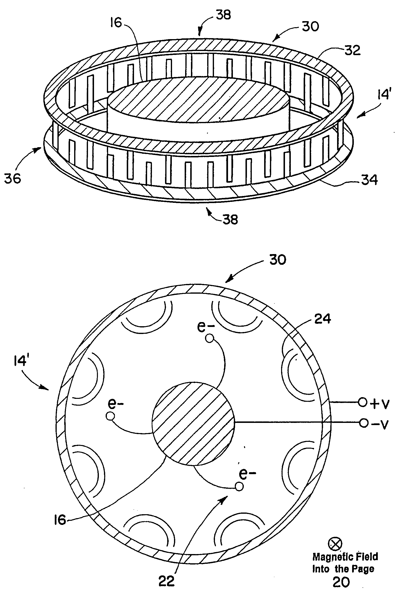
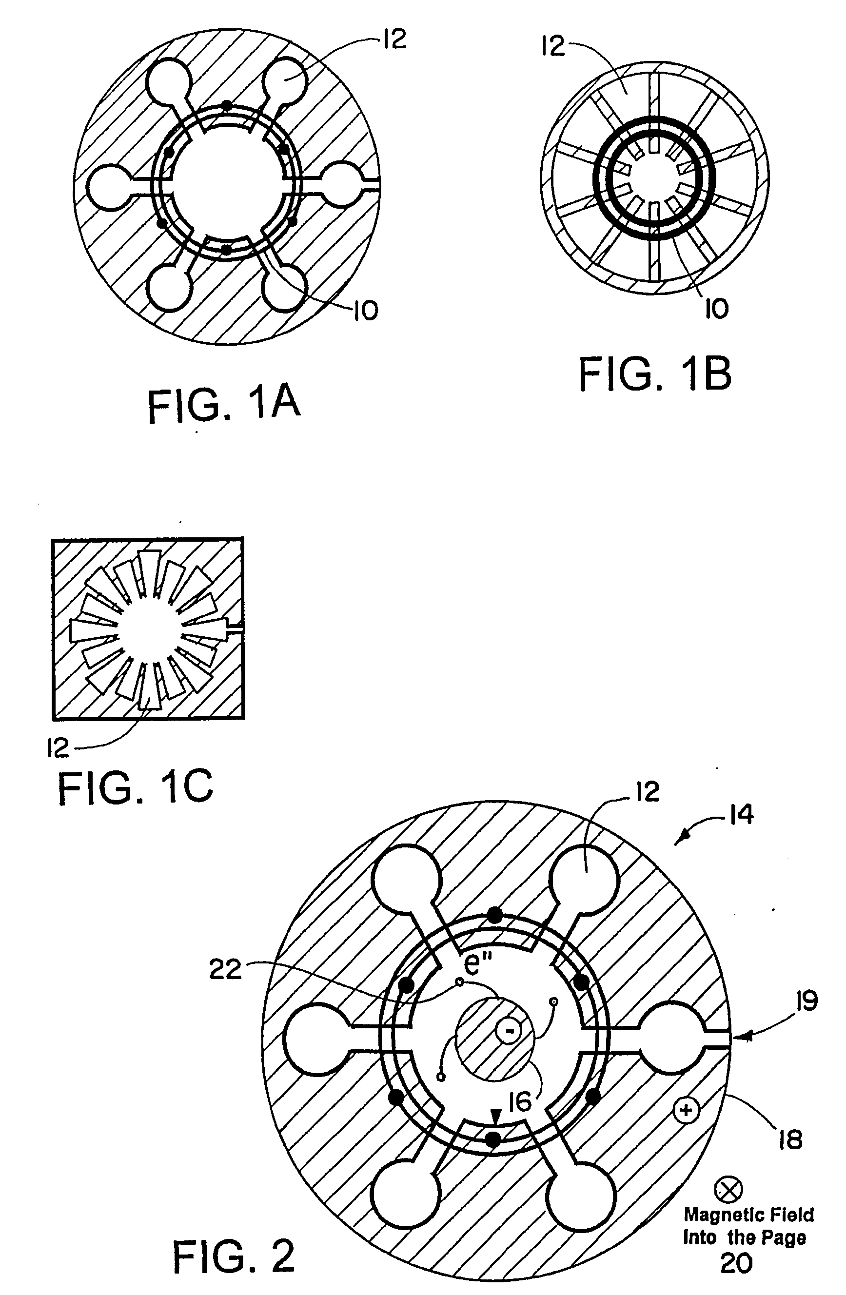
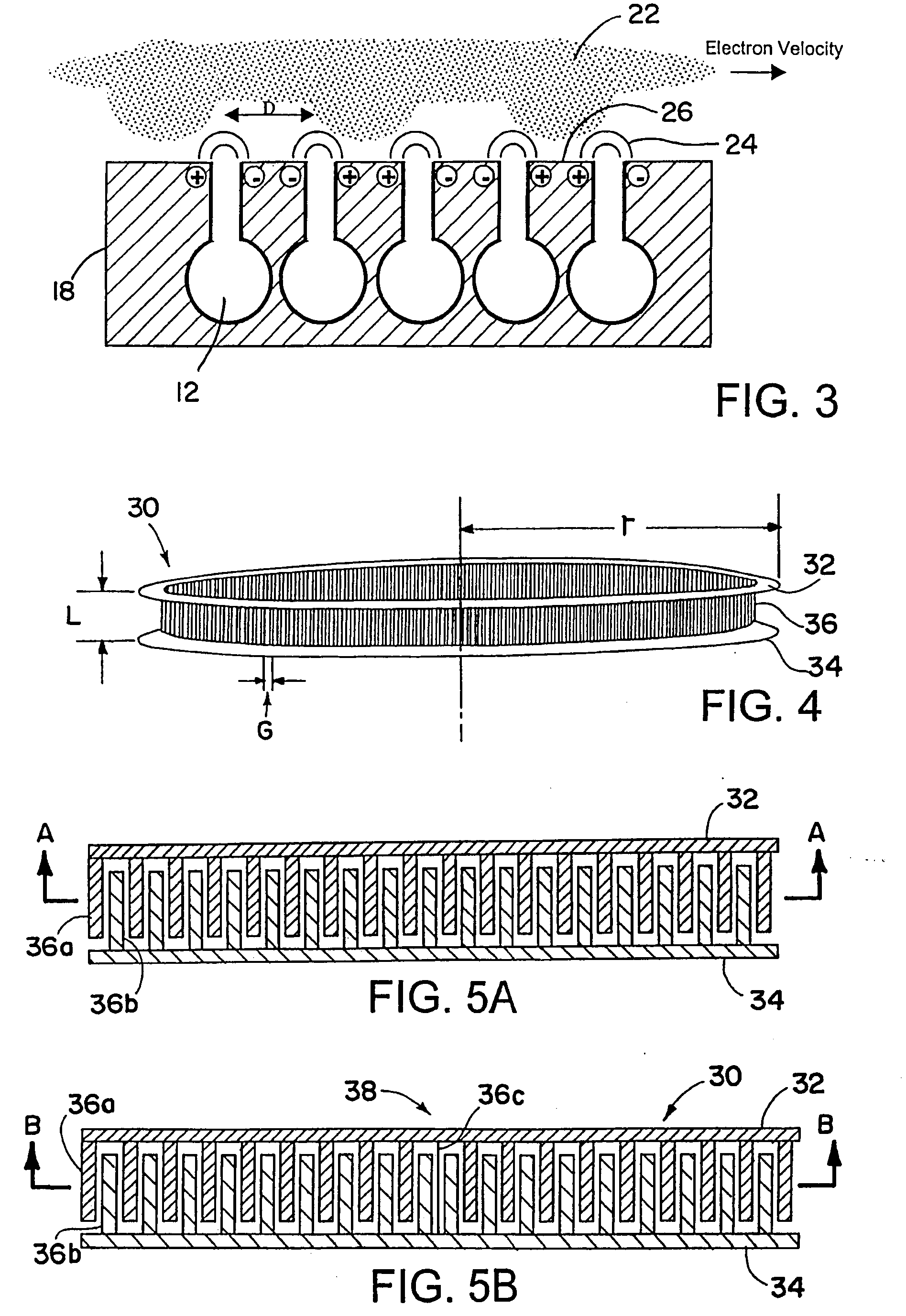
[0066]The applicants have discovered that large anodes, e.g., anodes with a circumference larger than one free-space wavelength, exhibit traveling waves along the inner circumference of the anode. In other words, the surface of the anode supports creeping waves that propagate around the circumference of the anode in both clockwise and counterclockwise directions. The traveling waves change phase as they travel around the anode and, at certain operating frequencies, look like standing waves, e.g., they are in phase with themselves as they complete one revolution around the anode. These stationary or standing modes perturb and control the phase of the individual resonators, thereby making pi-mode operat...


PUM


Abstract

An electromagnetic radiation source is disclosed that produces a single mode operation at a desired operating frequency. The electromagnetic radiation source is included in a wide variety of applications including a wireless power transmission system, a system for providing wireless/high-bandwidth communications in accordance with the present invention, a lighting system, an irradiation system, a weapons system, etc.

Description

RELATED APPLICATIONS[0001]This application is a continuation-in-part of U.S. patent application Ser. No. 10 / 982,591, filed Nov. 5, 2004, which is hereby incorporated herein by reference in its entirety.FIELD OF THE INVENTION[0002]The present invention relates generally to light sources, and more particularly to a high efficiency light source in the form of an optical magnetron and related applications.BACKGROUND OF THE INVENTION[0003]Magnetrons are well known in the art and have long served as highly efficient sources of microwave energy. For example, magnetrons are commonly employed in microwave ovens to generate sufficient microwave energy for heating and cooking various foods. The use of magnetrons is desirable in that they operate with high efficiency, thus avoiding high costs associated with excess power consumption, heat dissipation, etc.[0004]Conventional microwave magnetrons employ a constant electric and magnetic field to produce a rotating electron space charge. The electr...

Claims


Application Information

Patent Timeline
Patent Type & Authority Applications(United States)
IPC IPC(8): G01J1/42H01J25/55
CPCH01J23/02H01J25/56
Inventor SMALL, JAMES G.
Owner RAYTHEON CO
Why Eureka
Try Eureka