Low-power piezoelectric micro-machined valve

Active Publication Date: 2008-12-04
WISCONSIN ALUMNI RES FOUND +1
View PDF5 Cites 6 Cited by
  • Summary
  • Abstract
  • Description
  • Claims
  • Application Information

AI Technical Summary

Benefits of technology

[0004]The present invention provides an electrically actuated microvalve having a cross-plane piezoelectric actuator working to compress a pair of planar, micro-machined valve elements. The small displacement of the piezoelectric actuator is offset by perimeter augmentation of a valve seat between the valve elements. The result is a valve that can accommodate high actuation pressures and provide large flow modulation. A protective housing may be used to support the

Problems solved by technology

One challenge to the use of piezoelectric actuators is the relatively small displacement that they produce resulting in compara

Method used


Image

  • Low-power piezoelectric micro-machined valve
  • Low-power piezoelectric micro-machined valve
  • Low-power piezoelectric micro-machined valve

Examples


Embodiment Construction

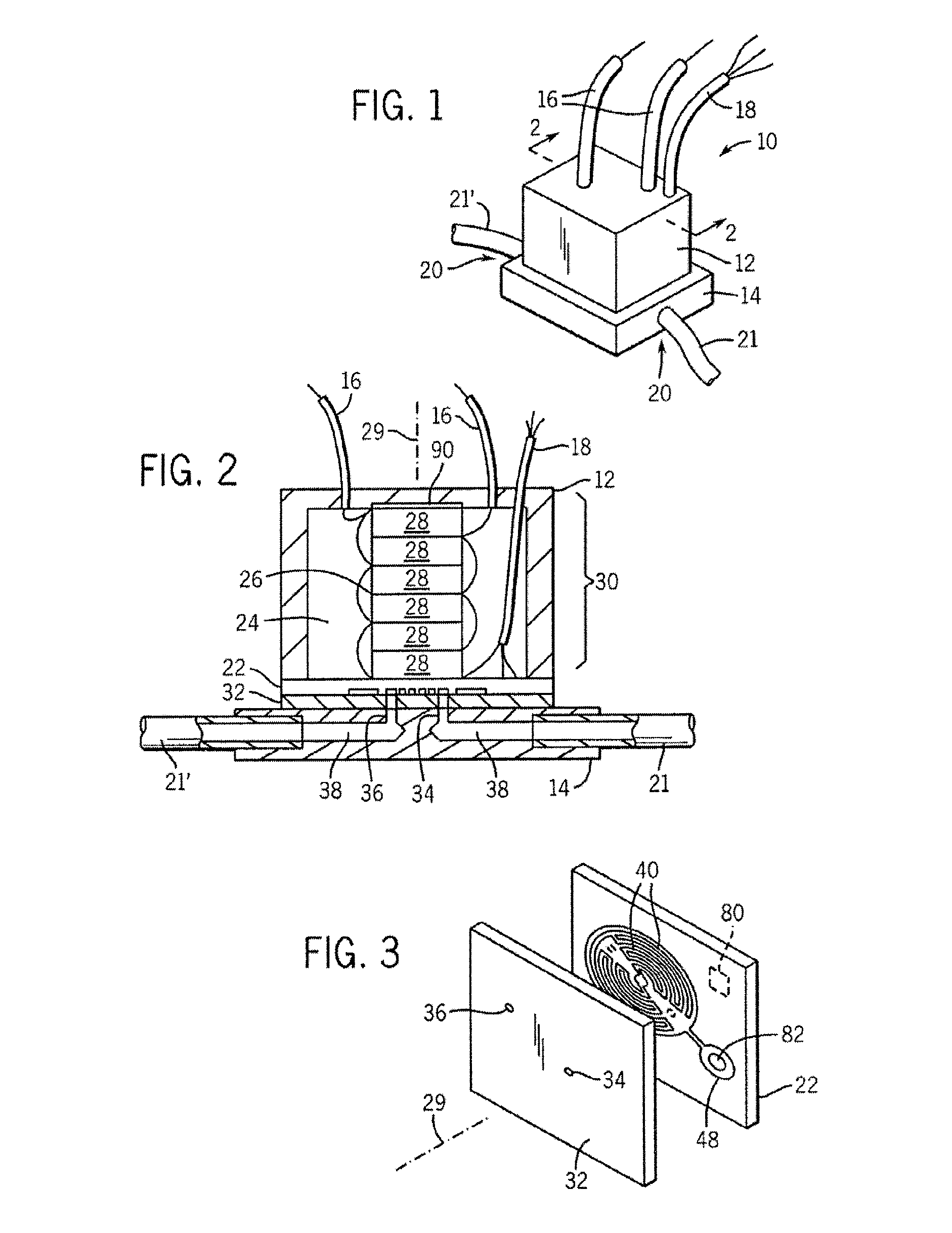
[0030]Referring now to FIG. 1, a microvalve 10 of the present invention may provide for a block-shaped housing 12, for example, defining a 1 cm cube. The microvalve 10 may fit against the upper surface of adapter plate 14, the latter providing connection points 20 to a standard-sized inlet tube 21 and outlet tube 21′ through which a fluid controlled by the valve can pass.

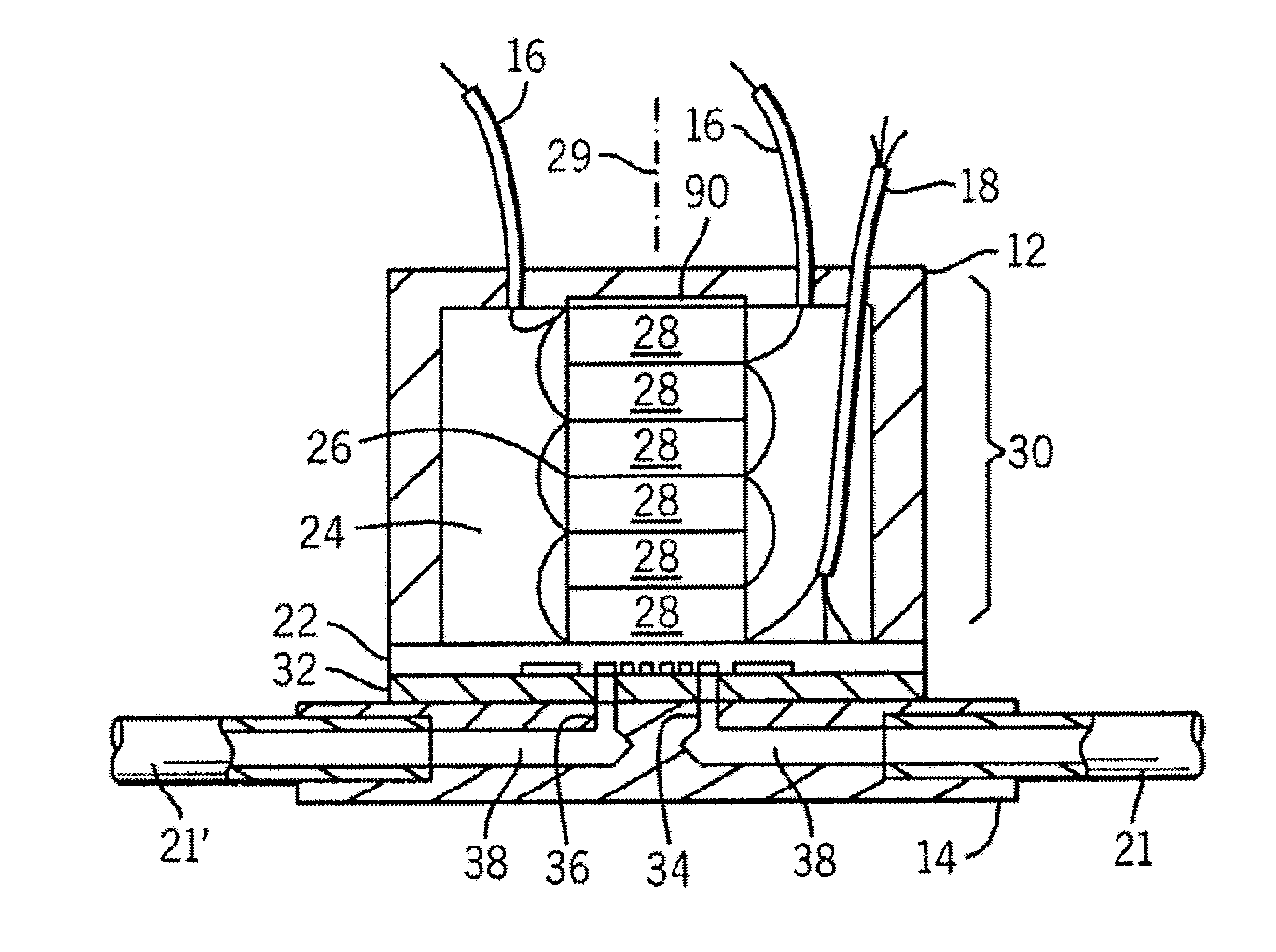
[0031]Referring also to FIG. 2, a lower, open face of the housing 12 may be bonded to the periphery of a continuous upper valve plate 22 thereby hermetically enclosing an actuator volume 24 within the housing 12. The housing 12 may be bonded to the upper valve plate 22 using a high temperature epoxy such as Stycast 2850FT epoxy.

[0032]Positioned within the actuator volume 24 is a piezoelectric stack 26 comprised of a set of piezoelectric elements 28 assembled together along a vertical axis 29 generally perpendicular to the upper surface of the upper valve plate 22. The piezoelectric stack 26 stretches from the upper ...


PUM


Abstract

A piezoelectric microvalve employs a valve element formed of hermetically sealed and opposed plates flexed together by a cross axis piezoelectric element. Large flow modulation with small piezoelectric actuator displacement is obtained by perimeter augmentation of the valve seat which dramatically increases the change in valve flow area for small deflections.

Description

CROSS-REFERENCE TO RELATED APPLICATIONSSTATEMENT REGARDING FEDERALLY SPONSORED RESEARCH OR DEVELOPMENTBACKGROUND OF THE INVENTION[0001]Compact, electrically actuated valves may be used in a variety of applications for example ranging from drug delivery to metering cryogenic gases in cooling systems for future space missions. Such valves may need to be highly reliable, resistant to extremes in temperatures, resistant to contamination from the environment, and energy efficient.[0002]One promising approach for the production of such valves constructs the valve body from micro-machined silicon using integrated circuit techniques. These micro-machined valve elements may be actuated by a piezoelectric actuator having very low power consumption and yet able to apply a very high force to the valve elements, necessary for high-pressure control in some applications.[0003]One challenge to the use of piezoelectric actuators is the relatively small displacement that they produce resulting in com...

Claims


Application Information

Patent Timeline
IPC IPC(8): F16K31/02
CPCF16K31/007F16K99/0001F16K99/0005F16K99/0048F16K2099/0074F16K2099/008F16K2099/0086Y10T137/7761
Inventor GIANCHANDANI, YOGESH B.NELLIS, GREGORY FRANCISKLEIN, SANFORD A.PARK, JOHN MOONEVANS, ALLAN THOMASTAYLOR, RYANBROSTEN, TYLER R.
Owner WISCONSIN ALUMNI RES FOUND
Why Eureka
Try Eureka