
White-light electro-luminescent device with improved efficiency

a technology of electroluminescent devices and white light, applied in the manufacture of electrode systems, electric discharge tubes/lamps, discharge tubes luminescnet screens, etc., can solve the problems of discontinuous change in color temperature, high energy efficiency of light sources, and luminance shi

Inactive Publication Date: 2008-12-04
NANOCO TECH LTD
View PDF9 Cites 27 Cited by
  • Summary
  • Abstract
  • Description
  • Claims
  • Application Information

AI Technical Summary

Benefits of technology

The present invention provides a white-light electroluminescent device with an adjustable color temperature that is substantially on a predetermined range of a Planckian locus within the 1976 CIE uniform chromaticity scale diagram. The device includes a first light-emitting element with a fixed ratio of at least two different species of emitters to produce a set of chromaticity coordinates at a predetermined white point substantially on the Planckian locus. A second light-emitting element with at least a single species of emitters produces a set of chromaticity coordinates. A controller adjusts the voltage or current associated with the first and second light-emitting elements to provide white light with a predetermined range of chromaticity coordinates substantially on the Planckian locus. The method of making the device includes the steps of forming electrode layers, selecting different species of emitters, and forming light-emitting layers with the selected emitters to achieve the predetermined white point. The technical effect of the invention is to provide a device with a unique color temperature that can be adjusted to produce warm or cool white light.

Problems solved by technology

Secondly, the light source must be highly energy efficient.
Unfortunately, this embodiment requires that either the blue or yellow LED be employed with the white LED.
Therefore, if the system is not calibrated properly or if one of the LEDs ages at a different rate than another, it is likely that a luminance shift will occur at the point where one LED is turned off and the other is turned on.
This has the potential to create a discontinuous change in color temperature as well as a sudden perceptual change in the perceived brightness of the lamp.
The proportion of light from the three light-emitting elements must be controlled to create the exact color coordinates of daylight sources, while factors such as unequal aging of the three lamps makes formation of daylight colors difficult.
Such a device does allow the possibility of color temperature variation during synthesis and manufacturing, however, it is achieved through a laborious selection of materials and these materials remain fixed after manufacture.

Method used


Image

  • White-light electro-luminescent device with improved efficiency
  • White-light electro-luminescent device with improved efficiency
  • White-light electro-luminescent device with improved efficiency

Examples


Embodiment Construction

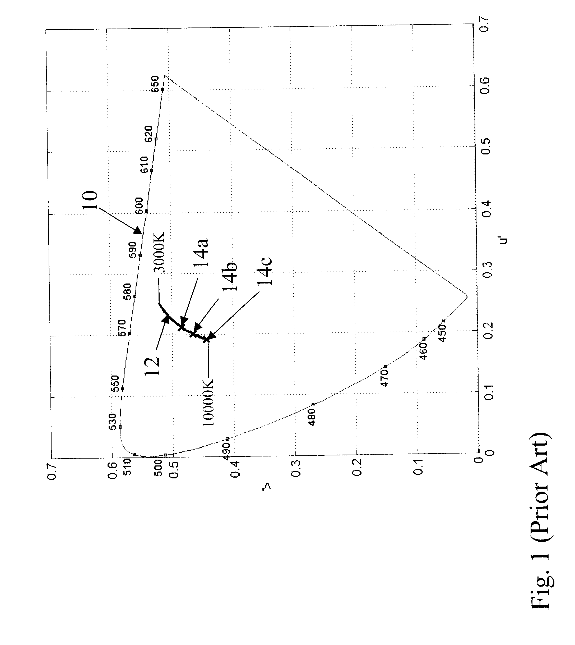
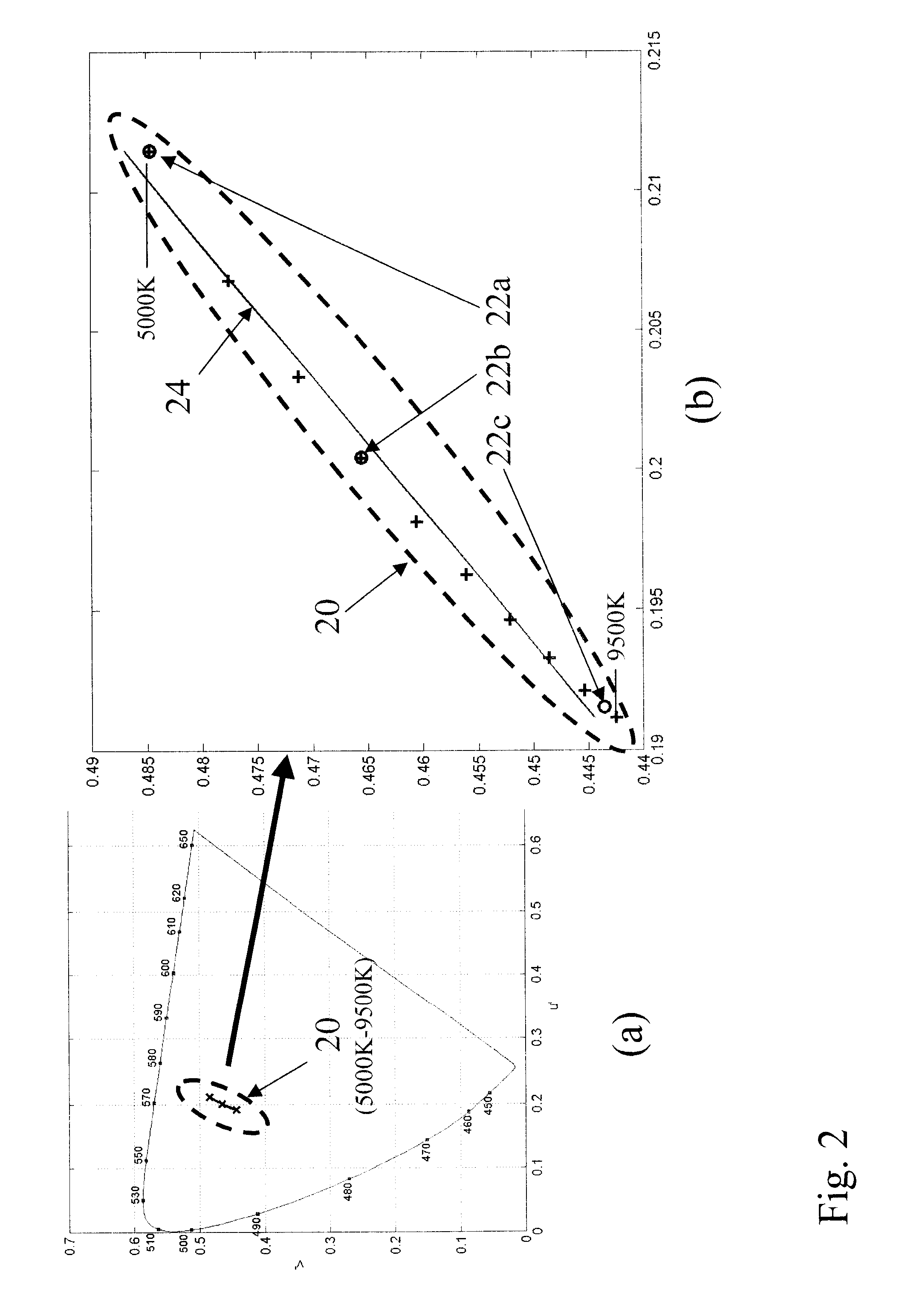
[0031]FIG. 2a shows a 1976 CIE uniform chromaticity scale diagram in which a group 20 of possible device white points is shown, all of which lie along the Planckian locus. In FIG. 2a, a range of blackbody radiator temperatures from 5000 K to 9500 K is shown (solid line) along with the three reference white points D50 22a, D65 22b and D93 22c mentioned earlier. This range of color temperatures is frequently used to set the white reference point of display or lighting devices. FIG. 2a shows the group 20 of possible device white points on the same scale as in FIG. 1. In accord with the present invention, FIG. 2b shows this family in more detail. It is observed that the group 20, whose individual data points are indicated in FIG. 2b by plus signs, are well fit by a straight line 24 over this region of the Planckian locus. To illustrate the present invention, FIG. 3 shows the linear fit 30 of the Planckian locus plotted on a 1976 CIE uniform chromaticity scale diagram, with the endpoints...


PUM


Abstract

A white-light electroluminescent device having an adjustable color temperature substantially on a predetermined range of a Planckian locus within the 1976 Commission Internationale de l'Eclairage (CIE) uniform chromaticity scale diagram. According to one embodiment, a first light-emitting element having a fixed ratio of at least two different species of emitters combined to produce a set of chromaticity coordinates at a predetermined white point substantially on the Planckian locus. A second light-emitting element having at least a single species of emitters produces a set of chromaticity coordinates. The set of chromaticity coordinates are positioned along a projected line extending from the Planckian locus and through the chromaticity coordinates of the first light-emitting layer. A controller adjusts the voltage or current associated with the first and second light-emitting elements to provide white light with a predetermined range of chromaticity coordinates substantially on the Planckian locus.

Description

FIELD OF THE INVENTION[0001]The present invention relates to inorganic LED devices employing quantum dot light-emitting layers. Specifically, the invention relates to inorganic white-light LED devices employing quantum dot white light-emitting layers, capable of producing a multiplicity of colors of white light that approximate blackbody or daylight whites, using two emitters.BACKGROUND OF THE INVENTION[0002]In recent years, light-emitting devices have included quantum-dot emitting layers to form large area light emission. One of the predominant attributes of this technology is the ability to control the wavelength of emission, simply by controlling the size of the quantum dot. As such, this technology provides the opportunity to relatively easily design and synthesize the emissive layer in these devices to provide any desired dominant wavelength, as well as control the spectral breadth of emission peaks. This fact has been discussed in a paper by Bulovic and Bawendi, entitled “Quan...

Claims


Application Information

Patent Timeline
Patent Type & Authority Applications(United States)
IPC IPC(8): H01J1/62H01J9/02
CPCH05B33/0821H05B33/0857H05B45/20H05B45/40
Inventor KANE, PAUL J.MILLER, MICHAEL E.COK, RONALD S.
Owner NANOCO TECH LTD
Learn More